Samsung Electronics
23
2) Key Scan
The grid waveform of each output is supplied to each button line through switching diode
(IN4148). The grid #1 signal goes to the setting button of refrigerator. Then, refrigerator button
is pressed, around 4.5V goes to IC05(UAN2981A) pin 8 through key input line. MICOM detects
the refrigerator button pressed after MICOM pin1 receives the signal.
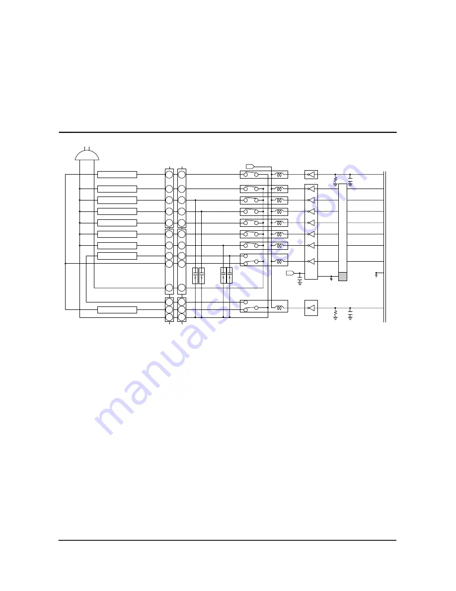
If MICOM outputs “high” signal to driver-IC(ULN 2803) according to each load operation
conditions, IC turns on and DC 12V flows to ground through the relevant relay coil. Then, core is
magnetized by the coil current, and relay contact switches on. When relay contact is on, AC POWER
is supplied to the relevant operation load, then which will be activated. If MICOM outputs “low”
signal, load operation stops with the relevant relay contact off.
8. Load Operation
9
7
5
3
1
9
7
5
3
1
5
3
1
9
7
5
3
1
9
7
5
3
1
5
3
1
IC06
18
1
11
8
12
7
13
6
15
4
15
3
17
2
18
1
17
2
Vcc GND
ULN2803
IC07
+12
RY01
RY02
RY03
RY04
RY05
RY06
RY07
RY08
R03
10K
C24
104
14
(COMP-COOL FAN) 16
18
19
21
22
(F-LAMP)
23
(F CIRCLE-FAN)
(COMP) 24
17
(R-DEF-HET)
SWING MOTOR
(R CIRCLE-FAN)
(R-LAMP)
9
AC1
R
C
I
N
E
T
W
O
R
K
+12
(DC12V)
C27
104
P05
P07
P11
P12
P14
P15
P17
P10
P06
P16
(F-DEF-HET) 15
C25
104
R02
10K
IC06
RY09
SPK1-4
SQ-1201
V12
CON8
CON10
CON9
RED
R-Defrost heater
COMP COOL FAN
SWING MOTOR
R-C/FAN
F-C/FAN
COMP.
R-LAMP
F-LAMP
F-Defrost heater


