61
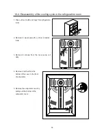
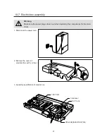
1. Disconnect the power cord.
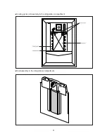
TEST S/W
Condenser
D/C Trans
PBA-SUB(INVERTER-PCB)
3. Assembly specification of electric box
2. Remove the cover of
electrical box with (–) driver.
Warning
Make sure the power plug is taken out when replacing the components for the main
PCB.
10-7. Electric box assembly
Summary of Contents for SR-L627EV
Page 5: ...5 4 Circuit Diagram 4 1 230V 240V 50Hz 220v 50Hz 60Hz 127V 60Hz 115V 60Hz ...
Page 10: ...5 4 Cool Air Circulation 10 ...
Page 27: ...2 3 Problem in refrigerator defrost sensor 2 4 Problem in freezer temperature sensor 27 ...
Page 28: ...2 5 Problem in freezer defrost sensor 28 ...
Page 31: ...4 2 When refrigerator fan R fan do not activate 31 ...
Page 32: ...4 3 When COMP cooling fan do not activate 32 ...
Page 34: ...34 ...
Page 36: ...6 2 If Beep sounds continuously 6 3 When original panel PCB do not activate 36 ...
Page 37: ...6 4 When buttons of panel PCB is not selected 37 ...
Page 43: ...9 Exploed View 9 1 Freezer room 43 ...
Page 45: ...LAMP FLUORESCENT 9 2 Refrigeration room 45 ...
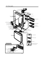
Page 48: ...SR L627EV SR L677EV 9 3 Door parts 48 ...
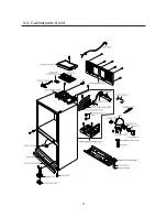
Page 51: ...9 4 Cabinet parts unit 51 ...
Page 56: ...56 6 Remove the housing of wires ...
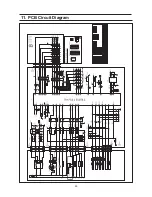
Page 63: ...63 11 PCB Circuit Diagram ...
Page 66: ...66 ...
Page 67: ...67 ...
Page 68: ...68 ...
Page 69: ...69 ...
Page 70: ...70 ...
Page 71: ...71 ...
Page 72: ...72 ...
Page 73: ...73 ...
Page 74: ...74 ...
Page 75: ...75 ...
Page 76: ...76 ...
Page 77: ...77 ...
Page 78: ...78 ...
Page 79: ...79 ...
Page 80: ...80 ...
Page 81: ... Samsung Electronics Co Ltd November 2001 Printed in Korea Code No DA68 01130A REV 0 0 ...

