78_
troubleshooting
troubleshooting
PROBLEM
SOLUTION
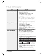
The “ACCESS DOOR ERR” message
appears when a RF ID card is being read.
1)
If the unit used to operate properly before, it is likely that there has been an electric shock
that damaged the internal memory and data.
Please initialize the unit as instructed in the manual.
2)
Check if the ID information has been entered correctly during its registration.
- Check if the value for RD is set correctly during the ID registration.
- If the RD value is set to “1”, the door opens only when READER 1 reads tthe card, and
does not open when READER 2 reads the card. If the card is presented to READER 2, the
“ACCESS DOOR ERROR” message will appear.
- If the RD value is set to “2”, the door opens only when READER 2 reads the card, and
does not open when READER 1 reads tthe card. If the card is presented to READER 1,
the “ACCESS DOOR ERROR” message will appear.
- If the RD value is set to either “0” or “3”, the door opens when either READER 1 or 2
reads the card.
3)
If the trouble persists after following the procedures above, contact a designated service center.
The buzzer keeps beeping.
1)
Check the door status. If the Door Contact sensor is connected and the Door Open
Timeout Alarm is selected, an alarm is given.
2)
Check the Door Contact sensor type: it must be NO/NC-type.
3)
Check the setup value for BZ in [10. OUTPUT T/S] under the [F5] menu.
This problem can occur if the time schedule code is set to value between 01 and 10 and
the present time is within the time zone of the selected schedule.
If the wrong time schedule is selected, change it to “00” (this can be set by PC software).
4)
Check the Tamper switch of the unit.
5)
If the trouble persists after following the procedures above, contact a designated service center.
The communication between the
controller and the Host PC fails.
1)
Please check the settings of the application software and the controller.
- Check if the COMM ID of the controller is registered on the application software.
- Set the different COMM ID when two or more controllers are installed.
- Check if the communication speed (57600bps is default) is the same as the setting on
the software.
- Make sure that the PC’s COM port is set correctly on the S/W.
2) Check the wiring for communication.
RS-232
RS-485 (Single)
Product
PC
Product
RS-485/232
Converter
PC
RX TX
RTX(-)
RTX(-)
The RS-232 cable
from the converter
TX
RX
RTX(+)
RTX(+)
GND
GND
RS-485(Multi Drop)
Product
Product
RS-485/232
Converter
PC
RTX(-) RTX(-)
RTX(-)
The RS-232 cable from
the Converter
RTX(+)
RTX(+)
RTX(+)
3)
It is recommended to use termination resistors of 120 Ohm between the RTX (+) and RTX
(-) wires when you are using the RS-485 communication. Apply the RS-485 converter to
the same resistors.
Consult a service center or an electric technician if you are not sure how to do it.
4)
When a multi-drop communication doesn’t work, test the communication one by one in
order from the fi rst one.
5)
If the trouble persists after following the procedures above, contact a designated service center.


