background image

COLOR CCD CAMERA

User Guide

10

COLOR CCD CAMERA

User Guide

11

Overview

Rear View

Bottom View

6

……

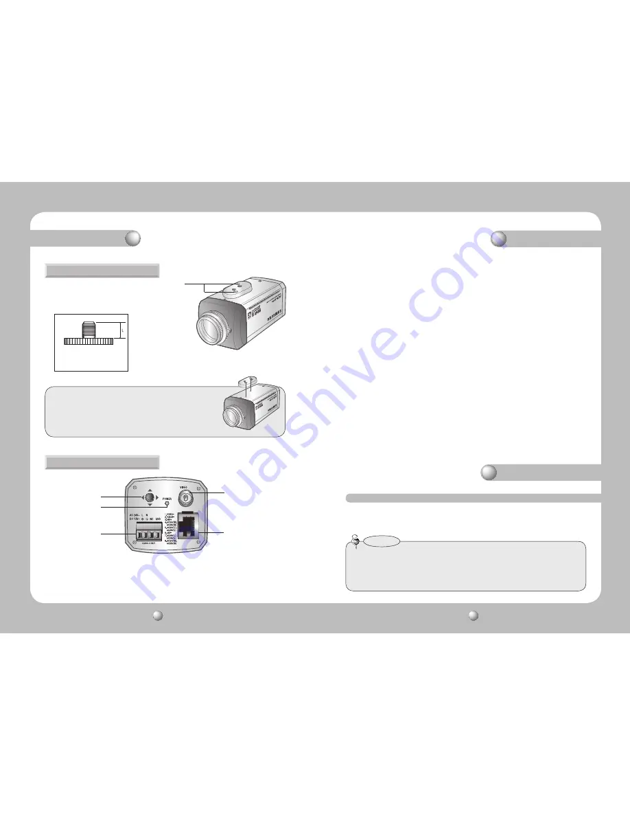
Tripod Mounting Bracket Screw Hole


Used to fix the camera on a bracket or tripod.  
The screw sizes for this hole are as follows:

1/4"-20 UNC (20 THREAD)
L:4.5mm±0.2mm (ISO standard), 
or 0.197" (ASA standard) 

You can separate the Tripod Mounting Bracket and install it on the 
top or bottom of the camera. Make sure to use the Tripod Mounting 
Bracket when fixing the camera to a bracket or tripod. Otherwise 
the camera may not be secure, or the internal circuitry of the 
camera may be damaged.

6

Overview

8


Power Video Output UTP Port


This port accepts power for the camera (AC 24V or AC 28V), outputs video, and 
facilitates RS-485 communication. 

9


Power LED


This lamp is lit when the camera is receiving power normally.


Power Input Terminal Block


If the UTP cable cannot be connected for power supply (distance over 300m(1000ft), 
for example), this cable is used instead for connecting DC 12V / AC 24V power to the 
camera using a separate adapter near by .


Video output terminal


Sends video signal and connects to the video input terminal of the monitor.

7


Function Setup switch


Display the menu on the screen and move the cursor in four directions to confirm 
status or after changing a selected item.

9

7

8

The lens is not supplied with this camera. Purchase a lens suitable for your environment. 
This camera accepts the auto iris lens and both C-and CS-mount lens.

•  To use the functions of this camera effectively it is recommended that a DC type Auto Iris 

lens is used.

•  Keep the lens surface clean, if it becomes contaminated with dirt or fingerprints the 

picture quality suffers.

Notes

Installation

LENS

Summary of Contents for SUB-2000 Series

Page 1: ...Before installing and operating this product please read this manual thoroughly Super High Resolution UTP Camera SUB 2000 UserGuide ENGLISH ...

Page 2: ...pment is operated in a commercial environment This equipment generates uses and can radiate radio frequency energy and if not installed and used in accordance with the instruction manual may cause harmful interference to radio communications Operation of this equipment in a residential area is likely to cause harmful interference in which case the user will be required to correct the interference ...

Page 3: ...alian French Spanish Russian Czech Polish Romanian Serbian Swedish Danish Turkish Portuguese SSNR3 Samsung Super Noise Reduction Function The high performanceW V DSP chip effectively removes low light gain noise and afterimage to provide clear images even in dark environments High Resolution By adopting a diagonal 6mm 1 3 410 000 NTSC pixel 470 000 PAL pixel SONY CCD the camera produces clear pict...

Page 4: ...m Therefore we can t compensate for material loss and or personalinjuriesbyrobbery fire naturaldisasterorothersuchevents Ignoring this information may result in material loss and or serious personal injuries including death Indicates NeverAllowed Ignoring this information may result in material loss and or a slight injuries Indicates No Disassembling Warning Attention Special Mark Messages Precaut...

Page 5: ... 2 C Mount adapter Please install this adapter when using a C Mount Lens 3 CS Mount adapter Please remove the C MOUNT adapter and then attach it 4 Back Focus clamp screw Please loosen the clamp screw with a screwdriver before adjusting the Back Focal length 5 Auto Iris Lens Connector Front View Side View Do not expose the camera to rain or other types of liquids If exposed to radioactivity the CCD...

Page 6: ...This lamp is lit when the camera is receiving power normally Power Input Terminal Block If the UTP cable cannot be connected for power supply distance over 300m 1000ft for example this cable is used instead for connecting DC 12V AC 24V power to the camera using a separate adapter near by Video output terminal Sends video signal and connects to the video input terminal of the monitor 7 Function Set...

Page 7: ...ockwise Installation When using a C Mount lens 3 Remove the cover of the auto iris lens connector plug and solder the lens cable to the connector pin of the plug No 3 Pin No 1 Pin Connector Lens cable No 4 Pin No 2 Pin 5 Please insert the connection plug that is connected to the auto iris lens cable into the auto lens connector which is located on the side of the camera Please take off the CCD pro...

Page 8: ...ive Receiver system setup please connect the adapter AC 24V or DC 12V directly to the camera Notes If the distance between the camera and the Power Supply exceeds 300m 1000ft please connect anAC 24V or DC 12V adapter to the Power Input Terminal Block Accessory Impressing power when the maximum transmission distance is exceeded may result in degradation of picture quality or even camera failure 1 S...

Page 9: ... RS 485 8 Brown POWER VIDEO RS 485 Copper Connector UTP Coating The SUB 2000 uses UTP cable to receive its power AC 24V or AC28V from the Power Supply Therefore a separate adapter is not required Please refer to the RJ 45 Connector Schematic Diagram UTP CABLE The camera uses UTP cable for transmitting video signals power and transferring RS 485 control data TIA EIA 568B RJ 45 Connector Schematic D...

Page 10: ...he Function Setup switch An item with the icon is unavailable due to function settings Notes Using this function you can control the screen brightness 1 When the SETUP menu screen is displayed select LENS by using the Function Setup switch so that the arrow indicates LENS 2 Select the connected lens type by using the Function Setup switch LENS Operating Your Camera Function Setup switch MAIN SETUP...

Page 11: ...he shutter speed to adjust the lens brightness IRIS SPEED DC Adjusts the Iris control speed of the DC lens If the control speed is too slow or fast please use this menu to adjust the speed MAIN SETUP 1 LENS DC 2 EXPOSURE EXPOSURE 1 When the SETUP menu screen is displayed select EXPOSURE by using the Function Setup switch so that the arrow indicates EXPOSURE 2 Select a desired mode using the Functi...

Page 12: ...mperature is between 1 700 K and 11 000 K OUTDOOR Select this when the color temperature is between 1 700 K and 11 000 K sodium light inclusion INDOOR Select this when the color temperature is between 4 500 K and 8 500 K MANUAL Select this to fine tuneWhite Balance manually SetWhite Balance first by using theATW orAWC mode After that switch to MANUAL mode fine tune theWhite Balance and the Functio...

Page 13: ...ASK COLOR TONE Change the color brightness of the masking area Black Red Blue Cyan Magenta TOP BOTTOM LEFT RIGHT Adjust the area to be enhanced 1 When the SETUP menu screen is displayed select SSDR by using the Function Setup switch so that the arrow indicates SSDR 2 Use the Function Setup switch to change the SSDR level in the sub menu according to the contrast between bright and dark areas SSDR ...

Page 14: ... Video Auto Iris Lens if you set the lens level to low automatic switching between Color and Black White may not occur When AGC in the EXPOSURE menu is OFF mode operates as selecting AUTO mode cannot be selected Notes You can display pictures in color or in black and white 1 When the SETUP menu screen is displayed select DAY NIGHT by using the Function Setup switch so that the arrow indicates DAY ...

Page 15: ...can change the OSD font color White Yellow Green Red Blue SHARPNESS As you increase this value the picture outline becomes stronger and clearer Adjust this value appropriately depending on the sharpness of the picture RETURN Select this to save the settings for the IMAGE ADJ menu and to return to the SPECIAL menu When the V REV or H REV mode is enabled the text on the screen does not flip If you i...

Page 16: ...ed and then press the Function Setup switch Notes change the gamma PED level and color gain in the sub menus CRT Please select this menu item when using a CRT monitor You can change the PED level color gain in the sub menus MOTION DET This product has a feature that allows you to observe movement of objects in 8 different areas on the screen and the words MOTION DETECTED appear on the screen when ...

Page 17: ...AREA SETUP 1 AREA AREA1 2 MODE OFF 3 MASK COLOR GREEN 4 MASK TONE 1 5 TOP 39 6 BOTTOM 79 7 LEFT 13 8 RIGHT 52 9 RETURN LANGUAGE You can select the menu language according to your requirements RETURN Select this to save the SPECIAL menu settings and return to the MAIN SETUP menu CAM ID Determines the camera s identification number between 0 and 255 BAUD RATE You can select 2400 4800 9600 19200 38 4...

Page 18: ... for the camera s UTP cable and the Camera Input UTP cable are normal The specification for this product may change without prior notice for product improvement This specification is based on a transmission distance of 500 meters in cases of long distance transmissions some degradation in picture quality may occur depending on the operating environment SUB 2000N SUB 2000P ELECTRICAL Input Voltage ...

Page 19: ...pean Representative Address Equipment Type Environment CCTV Camera Model Name SUB 2000P Beginning Serial NO C5436V3Z200001X Year of Manufacture 2010 02 01 Conformance to EN 55022 2006 EN 50130 4 2003 We the undersigned hereby declare that the equipment specified above conforms to the above Directive s Manufacturer SAMSUNGTECHWIN CO LTD LegalRepresentativeinEurope Signature Signature Full Name BONJ...

Page 20: ...COLOR CCD CAMERA User Guide 38 COLOR CCD CAMERA User Guide 39 MEMO MEMO ...

Page 21: ...orea 463 400 TEL 82 70 7147 8740 60 FAX 82 31 8018 3745 SAMSUNG TECHWIN EUROPE LTD Samsung House 1000 Hillswood Drive Hillswood Business Park Chertsey Surrey UNITED KINGDOM KT16 OPS TEL 44 1932 45 5300 FAX 44 1932 45 5325 SAMSUNG TECHWIN AMERICA Inc 1480 Charles Willard St Carson CA 90746 UNITED STATES Tol Free 1 877 213 1222 FAX 1 310 632 2195 www samsungcctvusa com SALES NETWORK ...

Reviews: