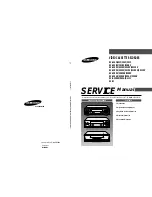


VIDEO CASSETTE RECORDER
SV-434F/431F/234F/231F
SV-233BV/231BV/230BV
SV-435XV/433XV/431XV/4313XV
SV-235XV/233XV/231XV/2315XV/2313XV
SV-230XV/230XDV/2300X
SV-435GV/430GV/235GV/230GV
SV-D2300G/D35G/D1111
SV-21
SERVICE
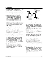
1. Precautions
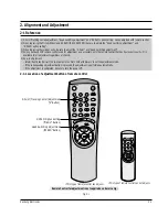
2. Alignment and Adjustment
3. Exploded View and Parts List
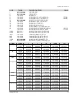
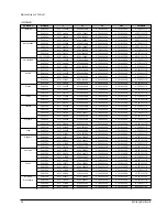
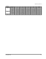
4. Electrical Parts List
5. Schematic Diagrams
Manual
VIDEO CASSETTE RECORDER
CONTENTS
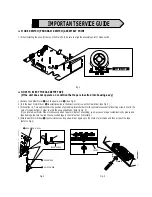
For mechanical disassembly and adjustment, refer to the “Mechanical Manual” (DX-9R AC68-00001A).
SERVICE MANUAL
SV
-434F/234F/233BV/230BV/435XV/235XV/230XV/435GV/235GV/D2300G/D35G/21
ELECTRONICS
© Samsung Electronics Co., Ltd.
AUG. 2000
Printed in Korea
AC68-01030A
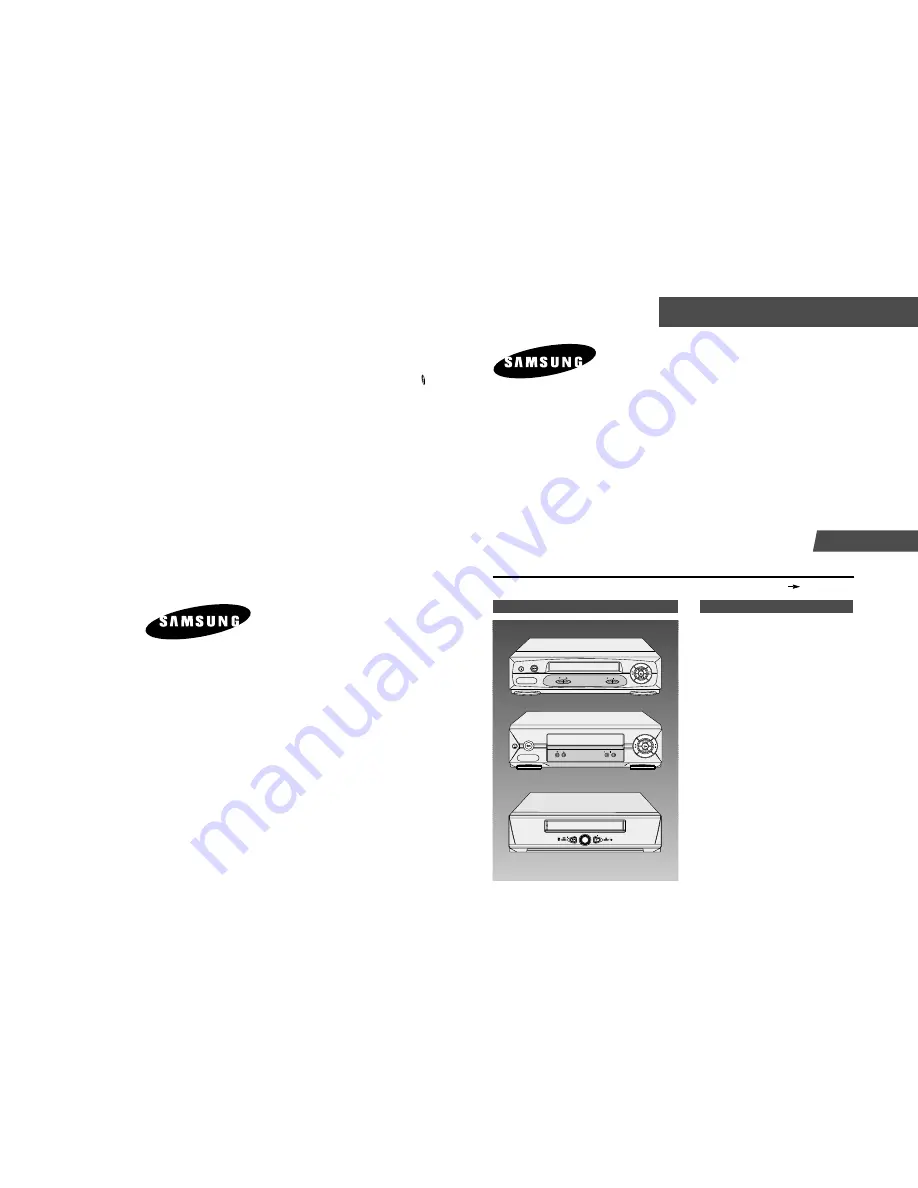
SV-434F/234F/435XV/235XV/233XV/435GV/235GV/D35G
SV-431F/231F/233BV/231BV/230BV/433XV/431XV/4313XV
SV-231XV/2315XV/2313XV/230XV/230XDV/430GV/230GV/21
SV-2300X/D2300G/D1111
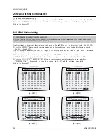
REC STOP
PROG
EJECT
STANDBY/ON
REW F.F
PLAY
EJECT
STANDBY/ON
REW F.F
PLAY
PROG
REC STOP
STANDBY/ON
PLAY / STOP
REC
EJECT
Summary of Contents for SV-21
Page 29: ...Schematic Diagrams Samsung Electronics 5 3 5 1 S M P S 230 Voltage ...
Page 30: ...Schematic Diagrams 5 4 Samsung Electronics 5 2 S M P S Free Voltage ...
Page 31: ...Schematic Diagrams Samsung Electronics 5 5 5 3 Power Drive ...
Page 32: ...Schematic Diagrams 5 6 Samsung Electronics 5 4 System Control Servo Display Front AV ...
Page 33: ...Schematic Diagrams Samsung Electronics 5 7 IC601 uPD784927 ...
Page 34: ...Schematic Diagrams 5 8 Samsung Electronics 5 5 Audio Video ...
Page 35: ...Schematic Diagrams Samsung Electronics 5 9 IC301 LA71598M ...
Page 36: ...Schematic Diagrams 5 10 Samsung Electronics 5 6 SECAM Option ...
Page 37: ...Schematic Diagrams Samsung Electronics 5 11 5 7 TM Block ...
Page 38: ...Schematic Diagrams 5 12 Samsung Electronics 5 8 VPS PDC OSD ...
Page 39: ...Schematic Diagrams Samsung Electronics 5 13 5 9 OSD Without VPS PDC ...
Page 40: ...Schematic Diagrams 5 14 Samsung Electronics 5 10 Input Output 2 Scart Jack ...
Page 41: ...Schematic Diagrams Samsung Electronics 5 15 5 11 Input Output 1 Scart Jack ...
Page 42: ...Schematic Diagrams 5 16 Samsung Electronics 5 12 Input Output RCA Jack ...
Page 43: ...Schematic Diagrams Samsung Electronics 5 17 5 13 Remote Control Multi TV ...
Page 44: ...Schematic Diagrams 5 18 Samsung Electronics 5 14 Remote Control VCR Only ...