


2-4
Samsung Electronics
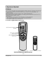
Alignment and Adjustment
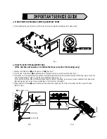
2-3 Head Switching Point Adjustment
1) Playback the alignment tape.
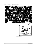
2) Intermittently short-circuit the two test point button on Main PCB to set the adjustment mode. (See Fig. 2-2)
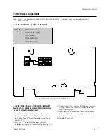
3) Press the “SPEED” button of remote control then adjustment is operated automatically. (See Fig. 2-1)
4) Turn the Power off.
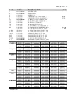
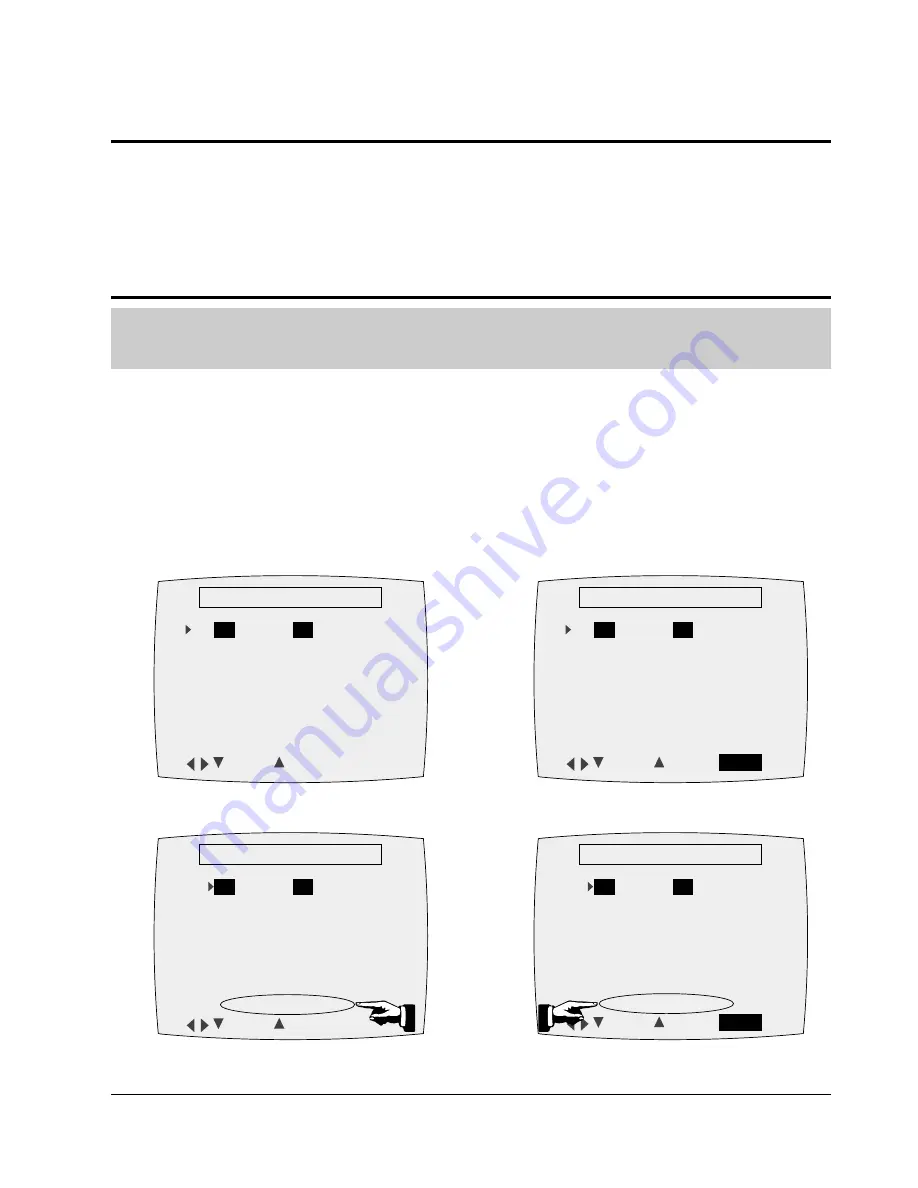
2-4 NVRAM Option Setting
1) Intermittently short-circuit the two test point button on Main PCB to set the adjustment mode. (See Fig. 2-2)
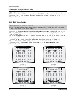
2) Press the “MENU” button on the remote control about 5 seconds then option setting display is appeared.
(See Fig. 2-4 and 2-5)
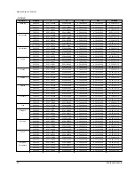
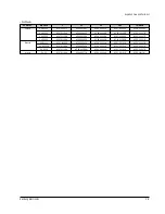
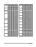
3) Select the option number (See Table 2-1 ; Page 2-5) of corresponding model with “FF” and “REW” button on
the remote control.
4) If selecting the option number is completed, press the “PLAY” button of remote control.
(If “PLAY” button is pressed, the selected number is changes reversed color. ; See Fig. 2-4 and 2-5)
5) Press the “OK (VCR)”, “MENU (VCP)” button of remote control again to store the option number.
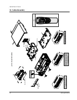
(“PLEASE WAIT” is displayed for a second as shown Fig. 2-6, 2-7 and this setting is completed.)
6) Turn the Power off.
1) NVRAM Option is adjusted at production line basically.
2) In case Micom (IC601) and NVRAM (IC605 ; EEPROM) is replaced, be sure to set the corresponding option number of the reqaired
model. (If the option is not set, the unit is not operated.)
01
02
03 04
05
06 07
08
09 10 11 12 13 14 15 16
17 18 19 20 21 22 23 24
25 26 27 28 29 30 31 32
33 34 35 36 37 38 39 40
41 42 43 44 45 46 47 48
49 50 51 52 53 54 55 56
**
OPTION DIODE
**
CNG : SAVE : OK
Fig. 2-4 (VCR)
01
02
03 04
05
06 07
08
09 10 11 12 13 14 15 16
17 18 19 20 21 22 23 24
25 26 27 28 29 30 31 32
33 34 35 36 37 38 39 40
41 42 43 44 45 46 47 48
49 50 51 52 53 54 55 56
**
OPTION DIODE
**
CNG : SAVE :
MENU
Fig. 2-5 (VCP)
01
02
03 04
05
06 07
08
09 10 11 12 13 14 15 16
17 18 19 20 21 22 23 24
25 26 27 28 29 30 31 32
33 34 35 36 37 38 39 40
41 42 43 44 45 46 47 48
49 50 51 52 53 54 55 56
**
OPTION DIODE
**
CNG : SAVE : OK
PLEASE WAIT
Fig. 2-6 (VCR)
01
02
03 04
05
06 07
08
09 10 11 12 13 14 15 16
17 18 19 20 21 22 23 24
25 26 27 28 29 30 31 32
33 34 35 36 37 38 39 40
41 42 43 44 45 46 47 48
49 50 51 52 53 54 55 56
**
OPTION DIODE
**
CNG : SAVE :
MENU
PLEASE WAIT
Fig. 2-7 (VCP)
Summary of Contents for SV-21
Page 29: ...Schematic Diagrams Samsung Electronics 5 3 5 1 S M P S 230 Voltage ...
Page 30: ...Schematic Diagrams 5 4 Samsung Electronics 5 2 S M P S Free Voltage ...
Page 31: ...Schematic Diagrams Samsung Electronics 5 5 5 3 Power Drive ...
Page 32: ...Schematic Diagrams 5 6 Samsung Electronics 5 4 System Control Servo Display Front AV ...
Page 33: ...Schematic Diagrams Samsung Electronics 5 7 IC601 uPD784927 ...
Page 34: ...Schematic Diagrams 5 8 Samsung Electronics 5 5 Audio Video ...
Page 35: ...Schematic Diagrams Samsung Electronics 5 9 IC301 LA71598M ...
Page 36: ...Schematic Diagrams 5 10 Samsung Electronics 5 6 SECAM Option ...
Page 37: ...Schematic Diagrams Samsung Electronics 5 11 5 7 TM Block ...
Page 38: ...Schematic Diagrams 5 12 Samsung Electronics 5 8 VPS PDC OSD ...
Page 39: ...Schematic Diagrams Samsung Electronics 5 13 5 9 OSD Without VPS PDC ...
Page 40: ...Schematic Diagrams 5 14 Samsung Electronics 5 10 Input Output 2 Scart Jack ...
Page 41: ...Schematic Diagrams Samsung Electronics 5 15 5 11 Input Output 1 Scart Jack ...
Page 42: ...Schematic Diagrams 5 16 Samsung Electronics 5 12 Input Output RCA Jack ...
Page 43: ...Schematic Diagrams Samsung Electronics 5 17 5 13 Remote Control Multi TV ...
Page 44: ...Schematic Diagrams 5 18 Samsung Electronics 5 14 Remote Control VCR Only ...