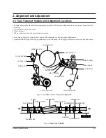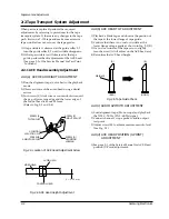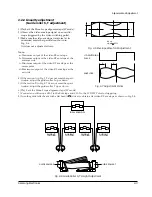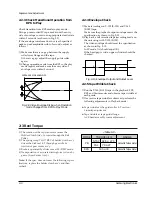
1-14
Samsung Electronics
Disassembly and Reassembly
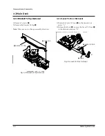
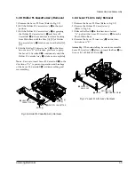
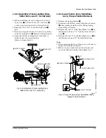
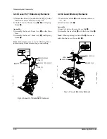
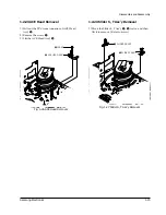
1-2-21 Lever #9 Guide Ass’y Removal
1) Remove the Spring #9 Guide
Œ
.
2) Lift the Lever #9 Guide AssÕy
´
in the direction of
arrow.
Note
:
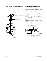
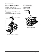
1) Take extreme care not to touch the grease on the
tape Guide Post.
2) After reinstalling, check the bottom side of the Post
#9 Guide to stick to the top side of Main Base.
´
LEVER #9 GUIDE ASS'Y
Œ
SPRING #9 GUIDE
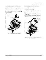
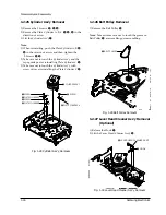
1-2-22 FE Head Removal
1) Remove the screw
Œ
.
2) Lift the FE Head
´
.
Œ
SCREW
´
FE HEAD
Fig. 1-24 Lever #9 Guide Ass’y Removal
Fig. 1-25 FE Head Removal
Summary of Contents for SV-425G
Page 10: ...2 6 Samsung Electronics Alignment and Adjustment MEMO ...
Page 18: ...Exploded View and Parts List 3 8 Samsung Electronics MEMO ...
Page 27: ...Schematic Diagrams Samsung Electronics 5 3 5 1 S M P S 230 Voltage ...
Page 28: ...Schematic Diagrams 5 4 Samsung Electronics 5 2 S M P S Free Voltage ...
Page 29: ...Schematic Diagrams Samsung Electronics 5 5 5 3 Power Drive ...
Page 30: ...Schematic Diagrams 5 6 Samsung Electronics 5 4 System Control Servo ...
Page 31: ...Schematic Diagrams Samsung Electronics 5 7 5 5 Audio Video ...
Page 32: ...Schematic Diagrams 5 8 Samsung Electronics 5 6 Secam ...
Page 33: ...Schematic Diagrams Samsung Electronics 5 9 5 7 Input Ouput ...
Page 34: ...Schematic Diagrams 5 10 Samsung Electronics 5 8 Remote Control Multi TV ...
Page 35: ...Schematic Diagrams Samsung Electronics 5 11 5 9 Remote Control VCR Only ...
Page 36: ...Schematic Diagrams 5 12 Samsung Electronics MEMO ...
Page 61: ...2 6 Samsung Electronics Alignment and Adjustment MEMO ...


