background image

Precautions

1-2

Samsung Electronics

11. High voltage is maintained within specified limits

by close-tolerance, safety-related components and
adjustments. If the high voltage exceeds the 
specified limits, check each of the special 
components.

12. Design Alteration Warning :

Never alter or add to the mechanical or electrical 
design of this unit. Example : Do not add 
auxiliary audio or video connectors. 
Such alterations might create a safety hazard. 

Also, any design changes or additions will void 

the manufacturerÕs warranty.

13. Hot Chassis Warning : 

Some TV receiver chassis are electrically
connected directly to one conductor of the AC 
power cord. If an isolation transformer is not 
used, these units may be safely serviced only if 
the AC power plug is inserted so that the chassis 
is connected to the ground side of the AC source.

To confirm that the AC power plug is inserted 
correctly, do the following : Using an AC 
voltmeter, measure the voltage between the
chassis and a known earth ground. If the reading
is greater than 1.0V, remove the AC power plug, 
reverse its polarity and reinsert. Re-measure the 
voltage between the chassis and ground.

14. Some TV chassis are designed to operate with 85 

volts AC between chassis and ground, regardless 
of the AC plug polarity. These units can be safely
serviced only if an isolation transformer inserted 
between the receiver and the power source.

15. Never defeat any of the B+ voltage interlocks. 

Do not apply AC power to the unit (or any of its
assemblies) unless all solid-state heat sinks are 
correctly installed.

16. Always connect a test instrumentÕs ground lead to

the instrument chassis ground before connecting 
the positive lead; always remove the instrumentÕs
ground lead last.

17. Observe the original lead dress, especially near 

the following areas : Antenna wiring, sharp 
edges, and especially the AC and high voltage 
power supplies. Always inspect for pinched, out-
of-place, or frayed wiring. Do not change the 
spacing between components and the printed
circuit board. Check the AC power cord for 
damage. Make sure that leads and components 
do not touch thermally hot parts.

18. Picture Tube Implosion Warning : 

The picture tube in this receiver employs 
Òintegral implosionÓ protection. To ensure 
continued implosion protection, make sure that 
the replacement picture tube is the same as the 
original.

19. Do not remove, install or handle the picture tube 

without first putting on shatterproof goggles 
equipped with side shields. Never handle the 
picture tube by its neck. Some Òin-lineÓ picture
tubes are equipped with a permanently attached 
deflection yoke; do not try to remove such 
Òpermanently attachedÓ yokes from the picture 
tube.

20. Product Safety Notice :

Some electrical and mechanical parts have special
safety-related characteristics which might not be 
obvious from visual inspection. These safety 
features and the protection they give might be 
lost if the replacement component differs from the
original--even if the replacement is rated for 
higher voltage, wattage, etc.

Components that are critical for safety are 
indicated in the circuit diagram by shading, 
(       or       ).
Use replacement components that have the same 
ratings, especially for flame resistance and
dielectric strength specifications. A replacement 
part that does not have the same safety 
characteristics as the original might create shock, 
fire or other hazards.

Summary of Contents for SV-625X

Page 1: ...001A SERVICE MANUAL SV 627X 425X 223X 627F 425F 627B 225B 625G 425G 620I C80K C30K 120W SVR 629 ELECTRONICS Samsung Electronics Co Ltd JAN 1999 Printed in Korea AC68 00128A SV 627X 627B 620G 620G 620I C620K SVR629 SV 625X 623X 620X 425X 225X 627F 623F 425F 423F 223F SV 625B 623B 620B 225B 625G 425G 225G C10K SVR 623 SV C80K SV 621X 520X 421X 4215X 4213X 223X 221X 2215X 2213X SV 220X 620X 420X 220X...

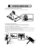
Page 2: ... driver See Fig 2 3 When Slider S T are approached in the position of unloading rotate holder Clutch counterclockwise after inserting screw driver in the hole of frame s bottom in order to wind the unwounded tape Refer to Fig 3 If you rotate Gear Worm Wheel continuously when tape is in state of unwinding you may cause a tape contamination by grease and tape damage Be sure to wind the unwounded tap...

Page 3: ...t exceed 0 5 milliamp Reverse the power plug prongs in the AC outlet and repeat the test 6 X ray Limits The picture tube is designed to prohibit X ray emissions To ensure continued X ray protection replace the picture tube only with one that is the same type as the original Fig 1 1 AC Leakage Test 7 Antenna Cold Check With the unitÕs AC plug disconnected from the AC source connect an electrical ju...

Page 4: ...strumentÕs ground lead to the instrument chassis ground before connecting the positive lead always remove the instrumentÕs ground lead last 17 Observe the original lead dress especially near the following areas Antenna wiring sharp edges and especially the AC and high voltage power supplies Always inspect for pinched out of place or frayed wiring Do not change the spacing between components and th...

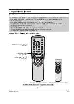
Page 5: ...nt regardless of chassis 5 How to adjustment Press the SW718 TEST button on Main PCB to set the adjustment mode If the corresponding adjustment button is pressed the adjustment is performed automatically If the adjustment is completed be sure to turn the power off 2 1 1 Location of adjustment button of remote control Fig 2 1 This type of remote control can adjust This type of remote control can no...

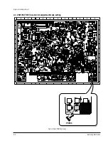
Page 6: ...2 2 Samsung Electronics Alignment and Adjustment 2 1 2 SW718 TEST location for adjustment mode setting Fig 2 2 Main PCB Top View PRESS ...

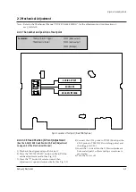
Page 7: ...WITCHING ENVELOPE 2 2 1 ACE Head Position X Point Adjustment See the 2 2 1 d ACE Head Position X Point Adjustment on page 2 2 of the Mechanical Manual 1 Playback the alignment tape Color bar 2 Press the ÒSW718 TEST Ó button on Main PCB to set the adjustment mode See Fig 2 2 3 Press the Ò5Ó button of remote control then adjustment is operated automatically See Fig 2 1 4 Connect the CH 1 probe to TP...

Page 8: ...to store the option number ÒPLEASE WAITÓ is displayed for a second as shown Fig 2 6 2 7 and this setting is completed 6 Turn the Power off 1 NVRAM Option is adjusted at production line basically 2 In case Micom IC601 and NVRAM IC605 EEPROM is replaced be sure to set the corresponding option number of the repaired model If the option is not set the unit is not operated 01 02 03 04 05 06 07 08 09 10...

Page 9: ...in SV 627X 2 4 5 6 7 8 9 10 12 13 14 15 18 23 24 31 33 36 37 38 39 40 41 43 44 SV 625X 2 5 6 7 8 9 10 12 13 14 15 18 23 24 31 35 38 41 44 SV 623X 2 5 6 8 9 10 12 13 14 15 18 23 31 35 37 38 39 SV 621X 5 6 8 9 10 12 13 14 15 18 23 31 35 37 38 39 SV 520X 2 5 6 7 8 9 10 12 13 18 23 24 31 35 37 38 39 SV 425X 2 5 6 7 8 12 18 23 24 31 35 38 SV 421X 5 8 12 18 23 31 35 40 SV 225X 2 5 6 7 18 23 24 31 35 38 ...

Page 10: ... 39 40 41 44 SV 625X 2 5 6 7 8 9 10 12 13 14 15 18 23 24 29 30 32 35 38 41 44 SV 621X 5 6 8 9 10 12 13 14 15 18 23 29 30 32 35 37 38 39 SV 425X 2 5 6 7 8 12 18 23 24 29 30 32 35 38 SV 421X 5 8 12 18 23 29 30 32 35 40 SV 225X 2 5 6 7 18 23 24 29 30 32 35 38 SV 220X 18 29 30 32 35 40 SV 2253X 2 5 6 7 18 23 24 29 30 32 35 39 40 Belgium SV 627X 2 5 6 7 8 9 10 12 13 14 15 18 23 24 30 33 36 37 38 39 40 ...

Page 11: ...35 38 41 48 SV 420G 8 11 12 18 25 31 35 40 48 SV 225G 2 5 6 7 11 18 23 25 31 35 38 48 SV 220G 11 18 25 31 35 40 48 SV 4253G 2 5 6 7 8 11 12 18 23 25 31 35 39 40 41 48 SV 4203G 8 11 12 18 25 31 35 37 39 40 48 SV 2203G 11 18 25 31 35 37 39 40 48 Malaysia SV C35K 5 6 9 10 11 18 19 23 25 26 29 31 32 35 39 40 Algeciras SV C620K 5 6 8 9 10 11 12 13 14 15 18 19 23 25 26 29 31 32 36 37 38 39 40 41 44 46 S...

Page 12: ...2 8 Samsung Electronics Alignment and Adjustment MEMO ...

Page 13: ...Samsung Electronics 3 1 3 Exploded View and Parts List 3 1 Cabinet Assembly 3 2 Mechanical Parts Top Side 3 3 Mechanical Parts Bottom Side Page 3 2 3 6 3 8 ...

Page 14: ...X 220X SV 620F 420F 220F 223B 220B SV 620G 420G 220G 56 55 S601A LD601A S602A VFD LED PCB S N A 102 157 1 21 22 1 51 SVR 623 SV C80K SV 6233X 2253X 2233X 120W SV 4253G 4203G 2203G C35K 21 22 1 SV C30K A2 NICAM PCB OPTION S N A 21 22 1 SV 625X 623X 620X 425X 225X SV 627F 623F 425F 423F 223F SV 625B 623B 620B 225B SV 625G 425G 225G C10K 21 22 31 1 52 52 158 SV 627X 627B 620G 600G 620I C620K SVR 629 ...

Page 15: ...0019A SV 223F AC97 00012A AC64 00054L AC64 30899E AC61 11061N AC39 10019A SV 220F AC97 00017A AC64 00054M AC64 30899E AC61 11061N AC39 10019A U K SV 627B AC97 00243A AC64 52158T AC64 00072A AC64 30899E AC61 11061K AC39 10022K SV 625B AC97 00018A AC64 00096C AC64 30899E AC61 11061K AC39 10022K SV 623B AC97 00018B AC64 00054N AC64 30899E AC61 11061L AC39 10022K SV 620B AC97 00019A AC64 00054P AC64 3...

Page 16: ... 00096F AC64 30899A AC61 11061P AC39 10019A SV 421X AC97 00028A AC64 00054W AC64 30899A AC61 11061P AC39 10019A SV 225X AC97 00025A AC64 00096K AC64 30899A AC61 11061P AC39 10019A SV 220X AC97 00030A AC64 00103E AC64 30899A AC61 11061R AC39 10019A SV 2253X AC97 00213C AC64 52169C AC64 30899A AC61 11061P AC39 10019A Norway SV 627X AC97 00245A AC64 52158U AC64 00072B AC64 30899E AC61 11061J AC39 100...

Page 17: ...AC64 00103J AC64 30899A AC61 11061L AC39 10019A SV 425G AC97 00155A AC64 00096Q AC64 30899A AC61 11061P AC39 10019A SV 420G AC97 00156A AC64 00103K AC64 30899A AC61 11061R AC39 10019A SV 225G AC97 00157A AC64 00096R AC64 30899A AC61 11061P AC39 10019A SV 220G AC97 00158A AC64 00103L AC64 30899A AC61 11061R AC39 10019A Poland SV 625G AC97 00153A AC64 00096P AC64 30899A AC61 11061J AC39 10019A SV 62...

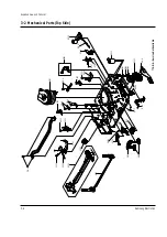
Page 18: ...2 Mechanical Parts Top Side G001 K250 K248 K110 K502 K350 K330 K182 K140 K490 K530 K240 G532 G420 G450 K546 G510 B410 B440 B444 B446 B448 B452 G527 G520 G480 G680 S N A S N A S N A S N A S N A G530 K340 B473 K188 G555 G546 S N A Service Not Available S N A ...

Page 19: ...423F 420F ONLY G420 AC66 80142A SLIDER SUPPLY ASSY X 9 TS X 9 G450 AC66 80141A SLIDER TAKE UP ASSY X 9 TS X 9 G480 AC33 10217H HEAD ACE ASSY X 9 G510 AC60 10518A SCREW TAP TITE PH SW ZW M2 6 L5 6 ZP G520 AC66 30539A LEVER 9 GUIDE ASSY X 9 TS X 9 G527 AC61 60553A SPRING 9 GUIDE ES SUS304 WPB OD3 1 0 G530 AC33 10217G HEAD FE VAA00000275 X 9 G532 AC60 10519A SCREW TAP TITE PH M2 6 L8 ZPC G546 AC66 30...

Page 20: ...d View and Parts List 3 8 Samsung Electronics 3 3 Mechanical Parts Bottom Side G542 B560 B484 B458 B500 B488 B462 OPTIONAL S N A S N A S N A S N A B456 K222 K200 K225 K221 B570 B238 S N A Service Not Available ...

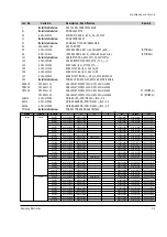
Page 21: ... TITE PH M2 6 L5 ZPC YE B484 AC66 20580A GEAR LOADING DRIVE POM SW 01 M1 0 Z32 B488 AC66 30543A LEVER S LOAD ASSY X 9 B500 AC66 30542A LEVER T LOAD ASSY X 9 B560 AC31 12017A MOTOR CAPSTAN DMVCMC07C X 9 B570 AC60 10514A SCREW CAPSTAN PH M2 6 L6 G542 AC66 60051A BELT PULLEY 5CM 70 2 2 71 3 X 9 K200 AC61 21012A HOLDER CLUTCH ASSY X 9 K221 AC66 20581A GEAR CENTER ASSY POM M O 5 HIGHT T K222 AC60 30306...

Page 22: ...Exploded View and Parts List 3 10 Samsung Electronics MEMO ...

Page 23: ... CARBON 220ohm 5 1 8W AA TP 1 8x3 2mm R1SD32 2001 000221 R CARBON 1 2KOHM 5 1 8W AA TP R1SR11 2003 000119 R METAL OXIDE 0 68ohm 5 2W AE TP 6x16mm R1SR12 2003 000264 R METAL OXIDE 300ohm 5 1W AD TP 4 3x12m R1SR14 2001 000003 R CARBON 330ohm 5 1 8W AA TP 1 8x3 2mm R1SS10 2006 000262 R CEMENT 2 7ohm 10 2W CB ST 7 5x11x20 R1SS13 2003 000148 R METAL OXIDE 100OHM 5 2W AE TP 6X16MM R1SS32 2001 000429 R C...

Page 24: ...8W AA TP 1 8x3 2m R1P108 2001 000449 R CARBON 2 2Kohm 5 1 8W AA TP 1 8x3 2m R1P109 2001 000038 R CARBON 390ohm 5 1 4W AA TP 2 4x6 4mm VFD MODEL ONLY R1P110 2001 000038 R CARBON 390ohm 5 1 4W AA TP 2 4x6 4mm VFD MODEL ONLY R1P111 2001 000110 R CARBON 10ohm 5 1 4 AA TP 2 4X6 4mm VFD MODEL ONLY R1P112 2001 000554 R CARBON 270ohm 5 1 8W AA TP 1 8x3 2mm R1P117 2001 000362 R CARBON 150ohm 5 1 8W AA TP 1...

Page 25: ...UDIO VIDEO PARTS C301 2401 001919 C AL 2 2UF 20 50V TP 4X7MM 5 C302 2301 000283 C FILM PEF 47nF 5 100V TP 7 3X7X3 2X5 5 C303 2401 000598 C AL 1uF 20 50V GP TP 4x7 5 C304 2202 000216 C CERAMIC MLC AXIAL 027NF 5 50V SL TP C305 2202 000164 C CERAMIC MLC AXIAL 18NF 10 50V Y5P TP C306 2202 000814 C CERAMIC MLC AXIAL 390pF 10 50V Y5P TP C307 2202 000162 C CERAMIC MLC AXIAL 015NF 5 50V SL TP C308 2202 00...

Page 26: ...ON 220ohm 5 1 8W AA TP 1 8x3 2mm R332 2001 000281 R CARBON 100ohm 5 1 8W AA TP 1 8x3 2mm R333 2001 000281 R CARBON 100ohm 5 1 8W AA TP 1 8x3 2mm R334 2001 000281 R CARBON 100ohm 5 1 8W AA TP 1 8x3 2mm R335 2001 000800 R CARBON 5 1Kohm 5 1 8W AA TP 1 8x3 2m R336 2001 000008 R CARBON 15Kohm 5 1 8W AA TP 1 8x3 2mm R339 2001 000258 R CARBON 1 8KOHM 5 1 8W AA TP MULTI SYSTEM R341 2001 001000 R CARBON 8...

Page 27: ...3 2mm R402 2001 000281 R CARBON 100ohm 5 1 8W AA TP 1 8x3 2mm R403 2001 000281 R CARBON 100ohm 5 1 8W AA TP 1 8x3 2mm R404 2001 000281 R CARBON 100ohm 5 1 8W AA TP 1 8x3 2mm R405 2001 000044 R CARBON 1 2Kohm 5 1 4W AA TP 2 4x6 4m R406 2001 000290 R CARBON 10KOHM 5 1 8W AA TP NON FRANCE REGION ONLY R407 2001 000449 R CARBON 2 2Kohm 5 1 8W AA TP NON FRANCE REGION ONLY R408 2001 000221 R CARBON 1 2KO...

Page 28: ... 33UH 5 2 4X3 4MM L810 2701 000181 INDUCTOR AXIAL 33UH 5 2 4X3 4MM L811 2701 000181 INDUCTOR AXIAL 33UH 5 2 4X3 4MM 2 SCART OPTION L812 2701 000181 INDUCTOR AXIAL 33UH 5 2 4X3 4MM 2 SCART OPTION L813 AC27 92001M INDUCTOR 70UH M RT BFS3565R2F L814 AC27 92001M INDUCTOR 70UH M RT BFS3565R2F Q802 0504 000203 TR DIGITAL KSR1004 NPN 300mW 47K 47K TO CANAL OPTION Q803 0504 000203 TR DIGITAL KSR1004 NPN 3...

Page 29: ...GITAL KSR2001 PNP 300mW 4 7K 4 7K T Q6B03 0501 000398 TR SMALL SIGNAL KSC945 NPN 250mW TO 92 T Q6B04 0501 000616 TR SMALL SIGNAL KSC2328A Y NPN 1W TO 92L R6B01 2001 000384 R CARBON 160ohm 5 1 8W AA TP 1 8x3 2mm R6B02 2001 000362 R CARBON 150ohm 5 1 8W AA TP 1 8x3 2mm R6B03 2001 000362 R CARBON 150ohm 5 1 8W AA TP 1 8x3 2mm ASSY SUB A2 NICAM PAL COBRA OPTION S N A C4N01 2202 000848 C CERAMIC MLC AX...

Page 30: ...TO 92 T Q711 0501 000290 TR SMALL SIGNAL KSA643 Y PNP 500MW TO 92 Q712 0501 000290 TR SMALL SIGNAL KSA643 Y PNP 500MW TO 92 Q713 0501 000290 TR SMALL SIGNAL KSA643 Y PNP 500MW TO 92 Q714 0501 000290 TR SMALL SIGNAL KSA643 Y PNP 500MW TO 92 Q715 0501 000290 TR SMALL SIGNAL KSA643 Y PNP 500MW TO 92 Q716 0501 000290 TR SMALL SIGNAL KSA643 Y PNP 500MW TO 92 R701 2001 000290 R CARBON 10KOHM 5 1 8W AA T...

Page 31: ...101 DIODE SWITCHING 1N4148 100V 200mA DO 35 SH6S1 2101 000101 VR ROTARY 100Kohm 20 1 10W SIDE Refer to table below REMOCON ASSY Electrical Parts List Samsung Electronics 4 9 Loc No Part No Description Specification Remark Loc No Part No Description Specification Remark Region Country Models Part No Universal Remote Europe France SV 627F AC59 10419J YES SV 623F AC59 10425G NO SV 620F AC59 10419N NO...

Page 32: ... NO SV 220X AC59 10419Y NO Hungary SV 625G AC59 10419S YES SV 620G AC59 10419Y NO SV 425G AC59 10425J YES SV 420G AC59 10419Y NO SV 225G AC59 10419G NO SV 220G AC59 10419Y NO SV 4253G AC59 10425J YES SV 4203G AC59 10419Y NO SV 2203G AC59 10419Y NO Romania SV 625G AC59 10419S YES SV 620G AC59 10419Y NO SV 425G AC59 10425J YES SV 420G AC59 10419Y NO SV 225G AC59 10419G NO SV 220G AC59 10419Y NO Czec...

Page 33: ... PCB 5 1 S M P S 230 Voltage 5 2 S M P S Free Voltage 5 3 Power Drive 5 4 System Control Servo 5 5 Audio Video 5 6 Hi Fi 5 7 TM Block 5 8 SECAM 5 9 A2 NICAM 5 10 Input Output 5 11 OSD VPS PDC 5 12 OSD Without VPS PDC 5 13 Function Timer VFD AV Link 5 14 Function Timer LED 5 15 F A V Jack SRC Shuttle 5 16 Remote Control Multi TV 5 17 Remote Control VCR Only ...

Page 34: ... the electrostatically sensitive ES devices section of this service manual Note Do not use the part number shown on this drawing for ordering The correct part number is shown in the parts list may be slightly different or amended since this drawing was prepared Important safety notices Components identified with the mark have the special characteristics for safety When replacing any of these compo...

Page 35: ...Schematic Diagrams Samsung Electronics 5 3 5 1 S M P S 230 Voltage HI FI MONO ...

Page 36: ...Schematic Diagrams 5 4 Samsung Electronics 5 2 S M P S Free Voltage HI FI MONO ...

Page 37: ...Schematic Diagrams Samsung Electronics 5 5 5 3 Power Drive ...

Page 38: ...Schematic Diagrams 5 6 Samsung Electronics FROM TO F TIMER VFD LED FROM TO F TIMER LED FROM TO F TIMER VFD FROM TO F A V JACK FROM TO SHUTTLE 5 4 System Control Servo ...

Page 39: ...Schematic Diagrams Samsung Electronics 5 7 5 5 Audio Video ...

Page 40: ...Schematic Diagrams 5 8 Samsung Electronics 5 6 Hi Fi ...

Page 41: ...0X AC40 30072A TMDG2 103A PAL BG 181CH G I K MONO AC40 30072D TCMK0600PD08A PAL BG I DK 181CH G I K Hi Fi AC40 30072H TCMK0601PD08A PAL BG I DK HI FI I AC40 30072E TCMI0610PD08A PAL I UHF SECAM L B G AC40 30072J TCPL0601PD08A SECAM L B G 181CH RF MODULATOR AC40 20100L RF MODULATOR RMUP74055VC VCP PAL ...

Page 42: ...Schematic Diagrams 5 10 Samsung Electronics 5 8 SECAM ...

Page 43: ...Schematic Diagrams Samsung Electronics 5 11 5 9 A2 NICAM MAIN C B A A2 NICAM MSP3415D A2 ONLY MSP3405D A2 NICAM C B A ...

Page 44: ...Schematic Diagrams 5 12 Samsung Electronics 5 10 Input Output ...

Page 45: ...Schematic Diagrams Samsung Electronics 5 13 5 11 OSD VPS PDC ...

Page 46: ...Schematic Diagrams 5 14 Samsung Electronics 5 12 OSD Without VPS PDC ...

Page 47: ...Schematic Diagrams Samsung Electronics 5 15 5 13 Function Timer VFD AV Link V F D VFD AV LINK ...

Page 48: ...Schematic Diagrams 5 16 Samsung Electronics 5 14 Function Timer LED LED MODULE LED SINGLE ...

Page 49: ...SRC F AV JACK SHUTTLE APPLICATION MODELS SVR 623 SV C80K C10K APPLICATION MODELS SV 627B 627X 620I 620G 600G SVR 629 APPLICATION MODELS SV 627B 627X 620I C620K 620G 600G SVR 629 APPLICATION MODELS SV 627F 625F 623F 425F 423F 223F 625B 623B 620B 225B SV 625X 623X 620X 425X 225X 625G 425G 225G SVR 623 ...

Page 50: ...Schematic Diagrams 5 18 Samsung Electronics 5 16 Remote Control Multi TV ...

Page 51: ...Schematic Diagrams Samsung Electronics 5 19 5 17 Remote Control VCR Only ...

Page 52: ...Schematic Diagrams 5 20 Samsung Electronics MEMO ...

Page 53: ...sembly and Reassembly 2 Alignment and Adjustment VHS DECK CONTENTS 3 File with the SERVICE MANUAL MECHANICAL MANUAL DX 9R ELECTRONICS Samsung Electronics Co Ltd NOV 1998 Printed in Korea AC68 00001A MECHANICALManual ...

Page 54: ...ˆ Ø Fig 1 1 Top parts Location 1 Œ BRACKET FL TOP GEAR FL CAM ˇ MOTOR LOADING ASS Y LEVER FL ARM ASS Y ˆ HOLDER FL CASSETTE ASS Y Ø LEVER FL DOOR SLIDER FL DRIVE 1 Disassembly and Reassembly 1 1 Deck Parts Locations 1 1 1 Top View ...

Page 55: ... Parts Location 2 Œ FE HEAD PLATE CYLINDER C ˇ CYLINDER ASS Y PLATE CYLINDER B ˆ PLATE CYLINDER A Ø ACE HEAD ASS Y UNIT PINCH ASS Y LEVER 9 GUIDE ASS Y LEVER TENSION ASS Y BAND BRAKE ASS Y Ô DISK S REEL LEVER S BRAKE ASS Y Ò GEAR IDLE Ú LEVER IDLE Æ LEVER T BRAKE ASS Y ı DISK T REEL ...

Page 56: ...s 1 3 1 1 2 Bottom View Œ ˇ ˆ Ø Ô Fig 1 3 Bottom Parts Location Œ GEAR JOINT 1 GEAR JOINT 2 ˇ BRAKET GEAR MOTOR CAPSTAN ASS Y ˆ LEVER T LOAD ASS Y Ø GEAR LOADING DRIVE LEVER S LOAD ASS Y HOLDER CLUTCH ASS Y BELT PULLEY SLIDER CAM Ô SLEEVE TENSION ...

Page 57: ...e Take care not to change assembly direction Œ 2 SCREWS BRACKET FL TOP 1 2 2 Lever FL Door Removal 1 Rotate the Lever FL Door Œ in the direction of arrow ÒAÓ 2 Release the Hook remove the Lever FL Door Œ in the direction of arrow ÒBÓ HOOK Œ LEVER FL DOOR A B 1 2 Main Deck Fig 1 4 Bracket FL Top Removal Fig 1 5 Lever FL Door Removal ...

Page 58: ...mpletely Note Be sure to insert Lever FL Cassette R in the direction of ÒAÓ to prevent separation and breakage of the Lever FL Cassette R at disassembling and reassembling Œ HOLDER FL CASSETTE ASS Y LEVER FL CASSETTE R BOSS A BOSS B RAIL C RAIL D A B 1 2 4 Lever FL Arm Ass y Removal 1 Remove the Lever FL Door Refer to Fig 1 5 2 Remove the Holder FL Cassette AssÕy Refer to Fig 1 6 3 Release the Hoo...

Page 59: ...the direction of arrow Refer to Fig 1 8 Œ SLIDER FL DRIVE 1 2 6 Bracket Gear Gear FL Cam Gear Joint 1 2 Removal 1 Remove screw Œ 2 Lift the Bracket Gear 3 Remove the Gear FL Cam ˇ 4 Lift the Gear Joint 2 Gear Joint 1 ˆ Œ SCREW BRACKET GEAR ˇ GEAR FL CAM ˆ GEAR JOINT 1 GEAR JOINT 2 Fig 1 8 Slider FL Drive Removal Fig 1 9 Bracket Gear Gear FL Cam Gear Joint 1 2 Removal ...

Page 60: ...ng Point 3 Œ GEAR JOINT 1 GEAR JOINT 2 ˇ SLIDER CAM TIMING POINT 1 GEAR FL CAM GEAR WORM WHEEL POST TIMING POINT 2 TIMING POINT 3 1 2 8 Holder Worm Gear Worm Gear Worm Wheel Removal 1 Release the Hook A in the direction of arrow and remove the Holder Worm Œ 2 Remove the Gear Worm 3 Remove the Gear Worm Wheel ˇ After remov ing the Gear FL Cam as shown Fig 1 9 Note Secure the Hook A after installing...

Page 61: ...S Load Ass y Removal 1 Remove the Belt Pulley Refer to Fig 1 29 2 Remove the Gear Loading Drive Œ after releasing Hook A in the direction arrow as shown in detail drawing 3 Remove the Slider Cam 4 Remove the Lever T S Load AssÕy ˇ Œ GEAR LOADING DRIVE ˇ LEVER T LOAD ASS Y HOOK A SLIDER CAM LEVER S LOAD ASS Y Fig 1 12 Motor Loading Ass y Removal Fig 1 13 Gear Loading Drive Slider Cam Lever T S Load...

Page 62: ... 1 TIMING POINT 2 TIMING POINT 3 1 2 12 Lever Tension Ass y Band Brake Ass y Sleeve Tension Removal 1 Remove the Spring Tension Œ 2 In bottom side of Deck remove the Sleeve Tension after rotating it right or left as lifting locking edge of Sleeve Tension 3 Remove the side ÒaÓ of the Band Brake AssÕy in the direction of arrow ÒAÓ from the Lever Tension AssÕy ˇ 4 Remove the side ÒbÓ of the Band Brak...

Page 63: ...care not to be folded and trans formed spring Brake at removing or reinstalling ˇ SPRING BRAKE LEVER T BRAKE ASS Y Œ LEVER S BRAKE ASS Y HOOK A HOOK C HOOK B 1 2 14 Lever Idle Ass y Removal 1 Push the Lever Idle Œ in the direction of arrow ÒAÓ ÒBÓ 2 Lift the Lever Idle Œ Assembly 1 Apply oil in two Bosses of Lever Idle Œ 2 Assemble the Gear Idle with the Lever Idle Œ Note When replacing the Gear I...

Page 64: ... S T Reel Removal 1 Lift the Disk S T Reel Œ DISK T REEL Œ DISK S REEL 1 2 16 Holder Clutch Ass y Removal 1 Remove the Washer Slit Œ 2 Lift the Holder Clutch AssÕy HOLDER CLUTCH ASS Y Œ WASHER SLIT Fig 1 18 Disk S T Reel Removal Fig 1 19 Holder Clutch Ass y Removal ...

Page 65: ... Base 2 Lift the Lever Up Down AssÕy Œ about 35 degree Refer to Fig 1 21 3 Insert Ring of the Gear Center AssÕy in the Guide ˆ of the Lever Up Down AssÕy Œ 4 Insert the Gear Center AssÕy in the post Ø on Main Base 5 Push down the Lever Up Down AssÕy Œ for lock ing of the Hook Note 1 Take care not to separate and loose the Spring Up Down 2 When assembling the Gear Center AssÕy donÕt push down too m...

Page 66: ... 2 20 Unit Pinch Ass y Plate Joint Spring Pinch Drive Removal 1 Lift the Unit Pinch AssÕy Œ 2 Remove the Plate Joint from Lever Pinch Drive 3 Remove the Spring Pinch Drive ˇ Note 1 Take extreme care not to touch the grease on the Roller Pinch 2 When reinstalling be sure to apply grease on the post pinch roller Œ UNIT PINCH ASS Y PLATE JOINT ˇ SPRING PINCH DRIVE Fig 1 22 Guide Cassette Door Removal...

Page 67: ...ion of arrow Note 1 Take extreme care not to touch the grease on the tape Guide Post 2 After reinstalling check the bottom side of the Post 9 Guide to stick to the top side of Main Base LEVER 9 GUIDE ASS Y Œ SPRING 9 GUIDE 1 2 22 FE Head Removal 1 Remove the screw Œ 2 Lift the FE Head Œ SCREW FE HEAD Fig 1 24 Lever 9 Guide Ass y Removal Fig 1 25 FE Head Removal ...

Page 68: ...connector of ACE Head AssÕy 2 Remove the screw Œ 3 Lift the ACE Head AssÕy Œ SCREW ACE HEAD ASS Y 1 2 24 Slider S T Ass y Removal 1 Move the Slider S T AssÕy Œ to slot and then lift it to remove Refer to arrow SLIDER T ASS Y Œ SLIDER S ASS Y Fig 1 26 ACE Head Removal Fig 1 27 Slider S T Ass y Removal ...

Page 69: ...ylinder C 3 Take care not to touch the Cylinder AssÕy with screw driver at reinstalling the Plate Cylinder C ˆ SCREW CYLINDER ASS Y Œ SCREW PLATE CYLINDER C ˇ SCREW PLATE CYLINDER B Ø PLATE CYLINDER A 1 2 26 Belt Pulley Removal 1 Remove the Belt Pulley Œ Note Take extreme care not to touch the grease on Belt Pulley Œ at assembling or reassembling Œ BELT PULLEY Fig 1 28 Cylinder Ass y Removal Fig 1...

Page 70: ... 29 How to Eject the Cassette Tape If the unit does not operate on condition that is inserted into housing ass y 1 Remove the Holder worm Œ and the Gear Worm 2 Turn the Gear Worm Wheel ˇ counterclockwise with screw driver Refer to arrow Œ HOLDER WORM GEAR WORM SCREW DRIVER ˇ GEAR WORM WHEEL Fig 1 31 Motor Capstan Ass y Removal Fig 1 32 3 When Slider S T are approached in the position of unloading ...

Page 71: ...STAN SHAFT 9 GUIDE POST 3 GUIDE POST GUIDE ROLLER S T O O O O O O O CYLINDER ASS Y O O O O O O O O O FE HEAD O O O O O O O ACE HEAD O O O O O O O O O PINCH ROLLER O O O O O O O O O POST REEL S T 3 3 3 3 3 SLEEVE TENSION 3 3 3 3 3 POST CENTER 3 3 3 3 3 LEVER IDLE BOSS 2Point 3 3 3 3 3 CAPSTAN MOTOR PULLEY O O O O O BELT PULLEY O O O O O O O HOLDER CLUTCH ASS Y O O O O O O O O O GEAR CENTER ASS Y O ...

Page 72: ...LER GUIDE ROLLER S GUIDE ROLLER T 8 GUIDE POST 9 GUIDE POST CAPSTAN SHAFT ACE HEAD 3 GUIDE POST 2 Alignment and Adjustment 2 1 Tape Transport System and Adjustment Locations The tape transport system has been adjusted precisely in the factory Alignment is not necessary except for the following 1 Noise observed on the screen 2 Tape damage 3 Parts replacement in the tape transport system Lower flang...

Page 73: ...ghtly turn the screw A tilt adjust on the ACE head assÕy 4 Reconfirm the ACE head height Fig 2 5 Tape Guide Check 2 2 1 c AUDIO AZIMUTH ADJUSTMENT 1 Load alignment tape Mono scope and playback the NTSC 7KHz PAL 6KHz signal 2 Connect channel 1 scope probe to audio output test point 3 Adjust screw B to achieve maximum audio level See Fig 2 3 2 2 1 d ACE HEAD POSITION X POINT ADJUSTMENT 1 See page 5 ...

Page 74: ...he video RF envelope at the exit side 4 If the section A in Fig 2 7 does not meet the speci fication adjust the guide roller S up or down 5 If the section B in Fig 2 7 does not meet the speci fication adjust the guide roller T up or down Fig 2 6 Envelope Waveform Adjustment a a b c d c b d a 63 b c d Fig 2 7 Adjustment Points A B A B H D SWITCHING PULSE ENVELOPE 6 Play back the Mono Scope alignmen...

Page 75: ...ng with T 120 E 120 The video envelope should meet the specification as shown in Fig 2 10 In SP mode A should equal B If the head gap is wide upper cylinder should be checked A B Fig 2 10 Envelope Output and Output Level 2 2 5 Tape Wrinkle Check 1 Run the T 160 E 180 tape in the playback FPS RPS and Pause modes and observe tape wrinkle at each guide 2 If excessive tape wrinkle is observed perform ...

Page 76: ...cting it with Back Tension Meter 1 0mm 0 5mm ˇ LEVER TENSION ASS Y Œ DISK S REEL ADJUSTING ADJUSTING SLIT 1 3 Fig 2 13 Tension Pole and Back Tension Adjustment 1 Remove the holder cassette assÕy and then push the lever FL Arm R to the direction of loading 2 Push the lever tension drive Œ in the direction of arrow See Fig 2 11 3 Turn the gear worm wheel clockwise so that ÒTiming PointÓ of the slide...

Page 77: ...2 6 Samsung Electronics Alignment and Adjustment MEMO ...

Reviews: