Circuit Operating Descriptions
7-31
7-6 Linear Audio
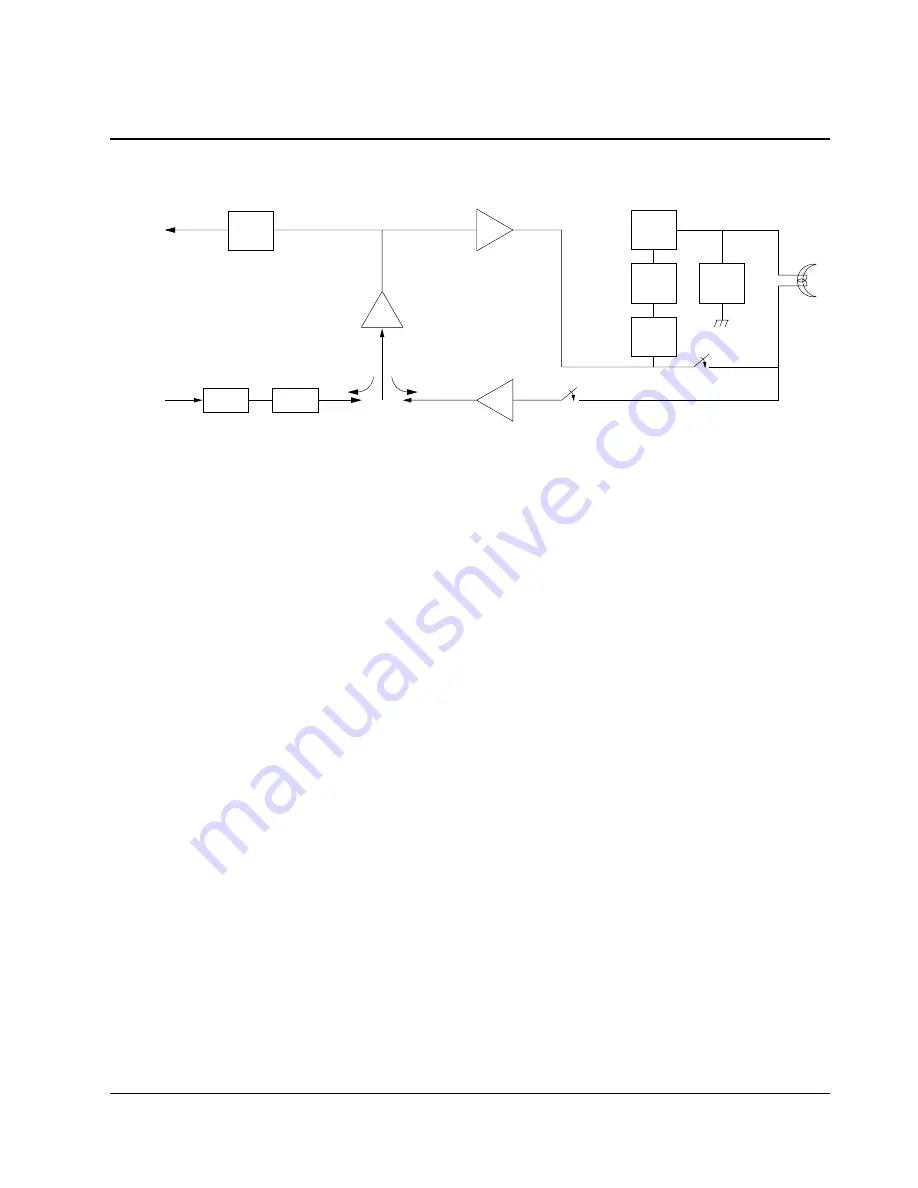
(1) Block Diagram
INPUT
ATT
ALC
LPF
12KHz
OUTPUT
OSD
BIAS
CTL
HPF
60KHz
S/W
PB ON
REC ON
PB ON
PB
AMP
REC
AMP
LINE
AMP
E/E
PB
R/P
HEAD
Fig. 7-27 Block Diagram
(2) Block Description
1) ATT (Attenuation)
Line amp is shared between PB mode and E/E mode, which reduces the recorded signal by 20dB and resister.
2) ALC (Auto Level Control)
If the signal level is lower than the reference signal (-6dBm) level, the output signal will equal the input signal.
However, if the input signal is higher than the reference signal, the output will not equal the input and will gen
erate uniform signal.
* ALC Application Purpose : Since linear audio is in AM (amplitude modulation) and uses magnetic recording
device, it only records limited size and as the size of input signal increases, distortion increases. To prevent
this occurance, mark sure the signal does not get bigger even if the level of distortion repodly increases.
3) LINE AMP
Line amp’s gain is approximately 23dB. The purpose of the line amp is to amplify to 68dB in order to obtain the
recorded signal on the tape during playback. As the amp gain increases, the passband decreases, which enables
the amplification of low frequency. However, it is impossible to amplify frequency of 10KHz to 68dB with just
1 OPAMP. Therefore, to satisfy frequency and gain.
Line amp must be constructed into 2 steps of OP AMP. (gain is fixed within IC)
4) 12KHz LPF
There are various noises to signal output. The loudest noise is the “Video SYNC Frequency” of 15.734KHz
In order to eliminate the “Video SYNC Frequency”, “LPF” and “TRAP” are combined to “LPF”.
Summary of Contents for SV-DVD40
Page 82: ...Circuit Operating Descriptions 7 7 Fig 7 12 Block Diagram ...
Page 116: ...Circuit Operating Descriptions 7 41 3 Block Diagram Fig 7 38 LA70100M Block Diagram ...
Page 141: ...VCR Deck Operating Description 8 12 Samsung Electronics Fig 8 14 Mecha Timing Chart ...
Page 156: ...Samsung Electronics 11 1 11 Wiring Diagram ...
Page 158: ...Schematic Diagrams 12 2 Samsung Electronics 6 1 S M P S ...
Page 159: ...Schematic Diagrams Samsung Electronics 12 3 6 2 Power Drive ...
Page 160: ...Schematic Diagrams 12 4 Samsung Electronics DT701 6 3 Display Function ...
Page 161: ...Schematic Diagrams Samsung Electronics 12 5 6 4 System Control Servo ...
Page 162: ...Schematic Diagrams 12 6 Samsung Electronics 6 5 A V ...
Page 163: ...Schematic Diagrams Samsung Electronics 12 7 6 6 Hi Fi ...
Page 164: ...Schematic Diagrams 12 8 Samsung Electronics 6 7 A2 NICAM ...
Page 165: ...Schematic Diagrams Samsung Electronics 12 9 6 8 SECAM Option ...
Page 166: ...Schematic Diagrams 12 10 Samsung Electronics 6 9 OSD VPS PDC ...
Page 167: ...Schematic Diagrams Samsung Electronics 12 11 6 10 TM ...
Page 168: ...Schematic Diagrams 12 12 Samsung Electronics 6 11 Input Output ...
Page 169: ...Schematic Diagrams Samsung Electronics 12 13 6 12 DVD AV Decoder ...
Page 170: ...Schematic Diagrams 12 14 Samsung Electronics 6 13 DVD Servo ...
Page 171: ...Schematic Diagrams Samsung Electronics 12 15 6 14 DVD Audio Video ...


