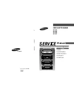


VIDEO CASSETTE RECORDER
SVR-639
SVR-633
SVR-630
SVR-537
SERVICE
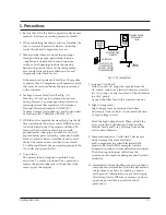
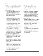
1. Precautions
2. Alignment and Adjustment
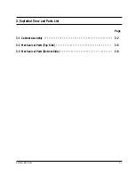
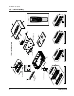
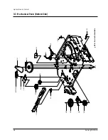
3. Exploded View and Parts List
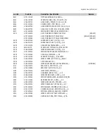
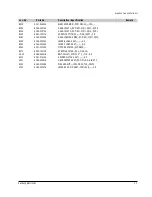
4. Electrical Parts List
5. Schematic Diagrams
Manual
VIDEO CASSETTE RECORDER
CONTENTS
For mechanical disassembly and adjustment, refer to the “Mechanical Manual” (DX-9R AC68-00001A).
SERVICE MANUAL
SVR-639/633/630/537
ELECTRONICS
© Samsung Electronics Co., Ltd.
APR. 2000
Printed in Korea
AC68-00887A
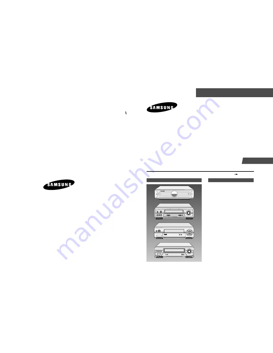
SVR-639
SVR-633
SVR-630
SVR-537
SRC PLAY
STANDBY/ON
REC STOP PLAY
PROG
EJECT
STANDBY/ON
LINE IN 2
REW
F.F
VIDEO L AUDIO R
EJECT
STANDBY/ON
REW F.F
PLAY
PROG
REC STOP
REC PLAY
STANDBY/ON EJECT STOP
SHARPNESS
REW
F.F
Summary of Contents for SVR-537
Page 17: ...Exploded View and Parts List 3 8 Samsung Electronics MEMO ...
Page 26: ...Schematic Diagrams Samsung Electronics 5 3 5 1 S M P S ...
Page 27: ...Schematic Diagrams 5 4 Samsung Electronics 5 2 Power Drive ...
Page 29: ...Schematic Diagrams 5 6 Samsung Electronics 5 4 Audio Video ...
Page 30: ...Schematic Diagrams Samsung Electronics 5 7 5 5 Hi Fi ...
Page 31: ...Schematic Diagrams 5 8 Samsung Electronics 5 6 RF VCP ...
Page 32: ...Schematic Diagrams Samsung Electronics 5 9 5 7 SECAM SVR 639 Only ...
Page 33: ...Schematic Diagrams 5 10 Samsung Electronics 5 8 Input Output 1 Scarrt Jack SVR 639 Only ...
Page 34: ...Schematic Diagrams Samsung Electronics 5 11 5 9 Input Output RCA Jack ...
Page 35: ...Schematic Diagrams 5 12 Samsung Electronics 5 10 OSD ...
Page 36: ...Schematic Diagrams Samsung Electronics 5 13 5 11 VFD Display SVR 639 ...
Page 37: ...Schematic Diagrams 5 14 Samsung Electronics 5 12 LED Module Display SVR 633 SVR 630 ...
Page 38: ...Schematic Diagrams Samsung Electronics 5 15 5 13 LED Single Display SVR 537 ...
Page 40: ...Schematic Diagrams Samsung Electronics 5 17 5 15 Remote Control Multi TV ...
Page 41: ...Schematic Diagrams 5 18 Samsung Electronics 5 16 Remote Control VCR Only ...
Page 66: ...2 6 Samsung Electronics Alignment and Adjustment MEMO ...