background image

SAMSUNG  ELECTRONICS CO., LTD

8-4

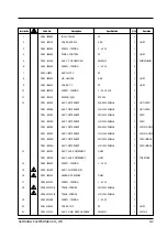
Location No.

Code No.

Description

Specification

Q'ty

Remarks

1

6002 - 000443

SCREW - TAPPING

2 - 4 X 20  STS

4

2

DC61 - 10403A

COVER - TUB

PP

1

3

DC66 - 50028B

CAP - PULSATOR

ABS

1

4

DC91 - 11258S

ASS'Y - SCREW  PULSATOR

M6 X 20.5

1

5

DC66 - 50183A

PULSATOR

PP

1

6

DC60 - 60003B

WASHER - PULSATOR

1

7

DC60 - 50004A

NUT - SPIN

ALDC  M24

1

8

DC60-60015A

WASHER-PLAIN

24.2 x 35

1

9

DC91 - 12010A

ASS'Y - BASKET  SPIN

SW80WI(P)

1

PP

9-1

DC91 - 12040A

ASS'Y - BLANCER

1

10

DC91 - 11774Q

ASS'Y - CASE  NET

2

11

DC61 - 30323A

TUB - OUTER

PP

1

12

DC62 - 10295A

HOSE - DRAIN

EPDM

1

PUMP

13

DC62 - 10294A

HOSE - PUMP

EPDM

1

PUMP

14

DC61 - 70063A

DIE - MOTOR

SBHG 1

1

15

DC60 - 20064C

SCREW - TAPPING

2 - 6.2 X 20

8

16

6046 - 000311

STAND  OFF

NYLON 66

5

17

DC91 - 10255B

ASS'Y - CASE  D.V

1

NO PUMP

17-1

DC91 - 10363B

ASS'Y - CUFF  HOSE

EPDM (169 mm)

1

NO PUMP

18

DC66 - 30027C

LINK

POM

1

BLK

19

DC31 - 20009F

MOTOR - DRAIN

220/240V  50/60Hz

1

DC31 - 20009G

MOTOR - DRAIN

110/120V  50/60Hz

1

20

DC91 - 11258M

ASS'Y - SCREW

M5 X 15

1

21

DC62 - 50011F

CONDENSER - M.F

400VAC  12 

uF

1

DC62 - 50011D

CONDENSER - M.F

220 VAC  42 

uF

1

22

DC61 - 40077A

HOLDER - CONDENSER

PP

1

23

DC60 - 20058B

SCREW - TAPPING

1 - 5 x 20

2

24

DC90 - 11120A

ASS'Y - WIRE  HARNESS

SW80W1P

1

PUMP

DC90 - 11155A

ASS'Y - WIRE  HARNESS

SW80W1

1

NO PUMP

25

DC61 - 60026A

CUSHION - MOTOR

FRPP

2

26

DC31 - 10025C

MOTOR - WASH

220/240V  50/60Hz

1

DC31 - 10025B

MOTOR - WASH

110/120V  50/60Hz

1

27

DC91 - 11258B

ASS'Y - SCREW

M8 x 40

2

28

DC66 - 10174A

PULLEY - MOTOR

50 Hz

1

DC66 - 10175A

PULLEY - MOTOR

60 Hz

1

29

DC60 - 50150A

NUT - HEX

M8 x 6.5

1

30

DC91 - 10057D

ASS'Y - SHAFT

SEM - 50D

1

31

DC60 - 80017B

PIN - LINK

M8 x 16

1

32

DC91 - 11258E

ASS'Y - SCREW

M8 x 40

4

33

DC66 - 10045B

BELT - V

M20.5

1

50 Hz

DC66 - 10045C

BELT - V

M20

1

60 Hz

34

DC61 - 40053A

SADDLE

SBHG1 - A

1

35

DC60 - 20064C

SCREW - TAPPING

6.2 x 20

2

Summary of Contents for SW80W1

Page 1: ... SP IN FU ZZY SO AK WO OL SPEEDY HIGH HO T CO LD WA TERSU PPLY WA TER LEVEL CO UR SE FUNCTIO N MEDIU M LO W EXT RALOW START H OLD POWER 1 Precautions 2 Specifications 3 Features 4 Operating Instructions 5 Schematic and Wiring Diagrams 6 Disassembly and Reassembly 7 Troubleshooting 8 Exploded Views 9 Power Cord ...

Page 2: ...sembly and wiring When assembling parts that use safety insulation material such as tube and tape or when installing internal wiring be sure to restore all parts and wiring to their original positions Take special care to avoid contact with sharp edges 1 2 3 Safety Checks after Servicing After servicing check to see that the screws parts and wiring are restored to their original positions and chec...

Page 3: ...olume of Water 160 l high level of water Rotation of the Pulsator 128rpm Rotation of the Spin Tub 770rpm Power Consumption Washing 330 W Spinning 270 W Dehydration Method Centrifugal dehydration type Drain Control Motor driven Applicable Water Pressure 0 5 kg f cm2 8 0 kg f cm2 Weight Gross 38kg Net 35kg Dimension Gross W 580mm X D 620mm X H 890mm Net W 560mm X D 580mm X H 915mm Accessories Water ...

Page 4: ... Front Adjustable Leg To control the height turn the adjustable leg 3 2 4 Connecting the Drain Hose 1 After pressing the joint ring a insert the drain hose b in the drain direction Same as pump model 2 Install the drain hose about 70 80cm above the ground for pump model SAMSUNG ELECTRONICS CO LTD 3 1 FULLY AUTOMATIC WASHING MACHINE WASH RINSE SPIN FUZZY SOAK WOOL SPEEDY HIGH HOT COLD WATER SUPPLY ...

Page 5: ... b with a gap about 5mm between them a b 3 Connect adaptor to the water tap by firmly tightening the screws Then turn part b following the arrow and put a and b toge ther a b 4 Connect the water supply hose to the adaptor Pull down part c of the water supply hose When part c is released the hose is automatically connected to the adaptor and makes a click sound c 5 Connect the other end of the wate...

Page 6: ... HOSE HOT FRONT CONTROL PANEL BLEACH INLET SPIN BASKET ADJUSTABLE LEGS MAGIC HAND PULSATOR FULLY AUTOMATIC WASHING MACHINE WA SH RIN SE SPIN FUZZY SOAK WO OL SPE EDY HIG H HO T CO LD WA TER SUPPLY WATER LEV EL CO URSE FUN CTION MEDIUM LOW EXTRALOW START HOLD POWER 4 Operating Instructions 4 1 Component Identification SAMSUNG ELECTRONICS CO LTD 4 1 ...

Page 7: ...r Supply option 1 Press this button to select water temperature 2 The selection order is Cold Cold Hot Hot Cold 3 Selecting the Wool Course automatically selects cold water to protect the wool fabric 4 2 5 Water Level 1 Press this button to select the water height 2 The selection order is High Medium Low Extra low 3 Selecting the Wool Course limits the water levels to high or medium 4 2 6 Course 1...

Page 8: ...ting If anykey is pressed after pressing the START HOLD key new Selection course is performed not related to previous course 4 This key is invalid during operation 4 3 4 Function Button 1 This key is valid except for weight sensing operation 2 After START HOLD during operation or under reset condition as pressing this key display is changing as follows 3 The beginning conditions are as follows whe...

Page 9: ...er stopping Motor compare the present water level to the water level selected if present water level the water level selected supply water to the water level selected if present water level the water level selected continue the washing or Rinsing operation But total time of supplementary water supplying is not over 30 seconds 4 4 3 Soak Function 1 This course works only when Soak washing is select...

Page 10: ...2 1 1 1 30 1 2 2 1 1 4 1 76 1 30 30 20 45 1 1 30 1 1 30 2 45 1 1 30 1 1 30 2 45 1 4 1 73 45 3 10 1 30 1 1 1 3 2 1 30 1 1 1 3 2 1 30 1 1 1 36 30 2 30 10 30 1 15 1 1 1 2 30 2 1 15 1 1 1 2 30 2 1 15 1 1 1 34 15 3 8 1 30 1 1 1 3 2 1 30 1 1 1 3 2 1 30 1 5 1 38 30 2 30 8 1 15 1 1 1 2 30 2 1 15 1 1 1 2 30 2 1 15 1 5 1 36 15 2 8 1 1 1 1 2 2 1 1 1 1 2 2 1 1 4 1 33 00 1 30 8 45 1 1 1 1 30 2 45 1 1 1 1 30 2 ...

Page 11: ... 1 15 1 1 30 1 2 30 2 1 15 1 1 30 1 2 30 2 41 2 00 20 1 1 1 30 1 2 2 1 1 1 30 1 2 2 39 1 30 20 45 1 1 30 1 1 30 2 45 1 1 30 1 1 30 2 37 3 2 1 30 1 1 30 1 3 2 1 30 1 5 1 23 30 2 30 2 1 15 1 1 30 1 2 30 2 1 15 1 5 1 22 2 2 1 1 1 30 1 2 2 1 1 4 1 19 30 1 30 2 45 1 1 30 1 1 30 2 45 1 4 1 18 3 00 20 1 30 1 1 30 1 3 2 1 30 1 1 30 1 3 2 1 30 1 5 1 51 30 2 30 20 1 15 1 1 30 1 2 30 2 1 15 1 1 30 1 2 30 2 1...

Page 12: ...5 Schematic and Wiring Diagrams SAMSUNG ELECTRONICS CO LTD 5 1 5 1 Wiring Diagram ...

Page 13: ...5 2 PCB and Pattern Diagram 5 2 WASHING MACHINE 5 Schematic and Wiring Diagrams ...

Page 14: ...severe vibration that might rock the washing machine 3 When replacing the suspension bar only use parts for this model 4 Since the length of the bar varies among on models installing the wrong size may cause severe vibration 5 Do not deform the check S W rod of the top cover 6 The installation of a deformed check S W rod will result in malfunction of the safety switch during severe vibration thus ...

Page 15: ... Pressure Sensor 3 Pull out the Air Hose PreWater Valve 1 Pull out the Lead Wire Terminals 2 Remove the Screws which fix the detergent box to the top cover PreChecker 1 Pull out the Lead Wire Terminals 2 Remove the two Screws 3 Lift out the Checker PreWire Harness 1 Pull out the Lead Wire Terminals from the PCB 2 Pull out the Lead Wire Terminals from the parts in back of the Top Cover 3 Remove the...

Page 16: ...up the Top Cover gently tilt the Top Cover back to expose the Tub Cover 2 Remove the four Screws fixing the Tub Cover 3 Remove the Bolt fixing the Pulsator 4 Remove the Spin Nut fixing the flange Shaft and the Shaft and pull out the Spin Basket 5 Lay down the Washing Machine with the rear side facing the floor 6 Remove the two Bolts fixing the Saddle 7 Remove the four Bolts fixing the Shaft using ...

Page 17: ...ssemble the box give three to four times of instantaneous shocks to the handle in the loosening direction then disassemble it by turning the handle when the nut is loosened 4 To disassemble the box strike the handle three or four times quick shocks to loosen it then complete the disassembly by turning the handle as the nut is loosened 5 Reassemble in reverse order 6 4 WASHING MACHINE 6 Disassembly...

Page 18: ...c ON 0 5sec OFF button cycle Another buttons do not work Water supply error No frequency change for 60 The buzzer sounds five times Press the Power minutes from water supply with a 0 5sec ON 0 5sec OFF button cycle No other buttons work Drain error Water level does not decrease to The buzzer sounds five times Press the Power the reset point within 6 minutes with a 0 5sec ON 0 5sec OFF button from ...

Page 19: ... PRESS the START HOLD key Aging test in driving part and then driving part and display are turned ON OFF for 1 second PRESS the COURCE key once Repeating 5 min dehydration and 3 min stop without draining PRESS the START HOLD key It read Lid open and unbalance and shows them It shows this on the indicator PRESS the COURCE key once Operate the washing cycle after suppling water PRESS the START HOLD ...

Page 20: ...soldered and insulation treated with vinyl tape or connected to the pressure connection terminal for drain treatment When connecting the lead wire take care not to let it touch hight components of metal sugared This is a wloow 5 Be sure to use only authorized replacement parts 6 AC 110V 220V is applied between T1 and T2 of the triac on the P C B Therefore touching the radiating plate accidentally ...

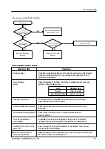
Page 21: ...d When pressing a selection button the buzzer does not sound or the LED does not display 7 4 WASHING MACHINE 7 Troubleshooting YES YES NO YES YES NO YES NO NO The power does not turn on Connect the power plug securely Replace the fuse Check the harness Replace the transformer Is the power plug connected Is the fuse blown Is the connection of the power trans harness OK Replace the PCB assembly Is t...

Page 22: ...plied Is the Start Hold button pressed after selecting the course Does the water valve make a Jee sound when water is supplied Is the connection of the water valve terminal all right Is the winding wire of the water valve electrically connected YES NO NO NO Is the fauct open Is the water supply stopped Isthere anyforeignmaterial attachedtothewaterhoseand thewatervalve filter Is the connection of t...

Page 23: ...ngout throughthedrainhosewith theoperationofthe drainvalve The water valve is defective Remove the foreign material in the water velve Air is leaking Check the connection and apply the adhesives Correct the bent hose Remove foreign materials such as drawn thread hair pin and buttons Check the drain valve YES YES YES NO NO Connect the terminal securely Turn off the power and then start again Is the...

Page 24: ...elt The pulsator does not rotate Does the water supply stop after filling to the specified level Does the motor make a woong sound Does the pulsator operate normally NO YES YES NO Is the connection of the water level sensor terminal all right NO Is water supplied Does the pulsator operate normally Is the V belt positioned correctly Replace the PCB assembly Replace the PCB assembly Now it is normal...

Page 25: ...n materials Noise coccurs during washing Does the noise occur from the inside of the washing tub NO NO NO Is there noise from the clutch Are there any foreign materials stuck between the washing net and the pulsator Is the position of the brake lever adjusted properly YES YES YES YES YES YES Adjust the clearance of the pulsator Contact noise due to the wear of motor bearing The noise is either the...

Page 26: ...r checking adjust the safety switch Is the terminal of the safety switch lifted up when closing the lid YES Replace the safety switch Is there continuity between the safety switch COM and the door terminal NO One or two unbalances automatically corrected through the process of water supply and washing The third time causes an unbalance error Spread the laundry evenly and start again Is the load un...

Page 27: ...Securely connect it Is the wire connecting the drain valve and the drain motor dropped out NO Is the outlet of the drain hose clogged NO Has there drawn thread or the like attached to the drain valve NO Is there any foreign material attached to the drain outlet Replace the PCB assembly YES Is the drain motor electrically connected YES Is operation of the drain motor alone possible YES Is the wire ...

Page 28: ...ign materials inside the washing machine Check for oil lubricant or In particular check the surrounding areas of driving units for oil lubricant water leakage leakage and check the moving parts of the drain valve for water leakage Checking the connection of the Check the power cord plug and receptacle for any damage Make sure they power cord comply with the working voltage Adjustment of horizontal...

Page 29: ...I N E WA SH RINS E SP IN FU ZZY SO AK WO OL SPEEDY HIGH HO T CO LD WA TERSU PPLY WA TER LEVEL CO UR SE FUNCTIO N MEDIU M LO W EXT RALOW START H OLD POWER 1 5 6 19 2 14 16 17 18 15 7 11 9 12 13 21 10 8 3 4 20 8 Exploded Views 8 1 WASHING MACHINE ...

Page 30: ...ENT 220 240V 50 60Hz 1 COLD DC91 11928D ASS Y DETERGENT 110 120V 50 60Hz 1 COLD DC91 11928E ASS Y DETERGENT 220 240V 50 60Hz 1 HOT COLD RINSE DC91 11928F ASS Y DETERGENT 110 120V 50 60Hz 1 HOT COLD RINSE DC91 11928G ASS Y DETERGENT 220 240V 50 60Hz 1 COLD RINSE DC91 11928H ASS Y DETERGENT 110 120V 50 60Hz 1 COLD RINSE 13 DC91 11923A ASS Y CASE DETERGENT L GRY 1 DC91 11923B ASS Y CASE DETERGENT L G...

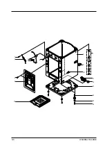
Page 31: ...8 3 WASHING MACHINE 8 Exploded Views 1 2 3 4 5 6 7 8 9 1 9 11 14 15 25 26 27 28 29 10 12 16 13 17 18 19 20 21 34 35 22 23 24 17 1 30 31 32 33 ...

Page 32: ...SS Y CUFF HOSE EPDM 169 mm 1 NO PUMP 18 DC66 30027C LINK POM 1 BLK 19 DC31 20009F MOTOR DRAIN 220 240V 50 60Hz 1 DC31 20009G MOTOR DRAIN 110 120V 50 60Hz 1 20 DC91 11258M ASS Y SCREW M5 X 15 1 21 DC62 50011F CONDENSER M F 400VAC 12 uF 1 DC62 50011D CONDENSER M F 220 VAC 42 uF 1 22 DC61 40077A HOLDER CONDENSER PP 1 23 DC60 20058B SCREW TAPPING 1 5 x 20 2 24 DC90 11120A ASS Y WIRE HARNESS SW80W1P 1 ...

Page 33: ...8 5 WASHING MACHINE 1 5 6 17 1 3 4 7 11 12 13 14 15 16 8 9 2 10 ...

Page 34: ...K PP 1 7 DC91 11378K ASS Y DAMPER FRONT WHT 2 DC91 11378L ASS Y DAMPER REAR YEL 2 8 DC92 11195A ASS Y PAINT SBHG1 A 1 9 DC61 20018J HANDLE PP 2 10 6406 000310 STAND OFF 7 11 DC90 11110A ASS Y PUMP DRAIN 220 240V 50Hz 1 DC90 11110B ASS Y PUMP DRAIN 220 60Hz 1 DC90 11110C ASS Y PUMP DRAIN 120 60Hz 1 12 DC60 20054F SCREW TAPPING 1 4 x 14 4 13 DC61 30321A BASE PP 1 14 DC61 50009A LEG ADJUST FRPP 2 15 ...

Page 35: ...A DC61 60035A DC39 10144A DC39 10001C DC61 60034A DC61 60055B DC61 60041A DC90 10065C WHITE BLACK GREEN WHITE BLACK GREEN BF3 BROWN BLUE YELLOW GREEN AP3 CP3 BROWN BLUE GREEN YELLOW CP2 EP3 WHITE BLACK GREEN EP2 CP2 D WHITE BLACK GREEN WHITE WHITE BLACK WHITE ...

Reviews: