11-2
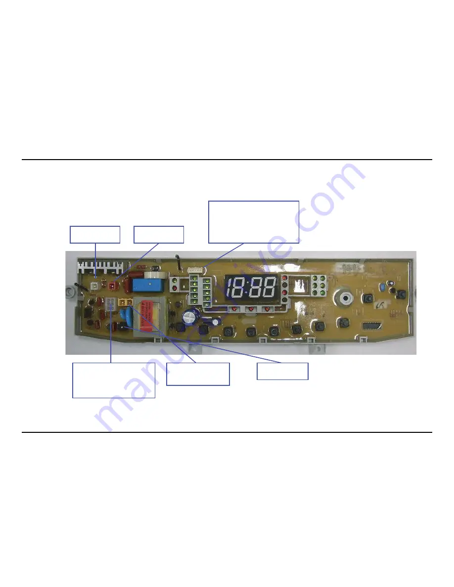
11-2. Connector & Relay Terminals Description
CN1 Component
Connected to Motor MR
CN3 Component
Connected to Motor ML
CN6 Component
1. Connected to water level senser (WL_1)
2. Connected to door checker (DOOR UNB)
3. Connected to water level senser (WL)
4. Connected to the ground (GND)
5. Connected to 5V (5V)
CN2 Component
1. Connected to hot valve (H/W)
3. Connected to rinse valve (RINSE)
4/5. Connected to drain motor (DRAIN)
6. Connected to cold valve (COLD)
CN5 Component
1. Connected to AC power
2. Connected to AC common
CN4 Component
Connected to AC power
Summary of Contents for SW82ASP
Page 22: ...4 3 ...
Page 23: ...4 4 Memo ...
Page 29: ...5 6 5 4 REASSEMBLY Reassembly procedures are in the reverse order of dissasembly procedures ...
Page 45: ...7 6 7 3 ASSY CASE A0086 U0061 A0282 I0039 I0040 I0040 B0073 B0072 B0012 B0044 B0070 ...
Page 48: ...8 2 Memo ...
Page 49: ...9 1 9 BLOCK DIAGRAM ...
Page 50: ...9 2 Memo ...
Page 51: ...10 1 10 WIRING DIAGRAM ...
Page 52: ...10 2 Memo ...
Page 55: ...12 1 12 SCHEMATIC DIAGRAMS This Document can not be used without Samsung s authorization ...
Page 56: ...12 2 Memo ...
Page 60: ...13 4 Memo ...


