background image


SyncMaster 400T

Summary of Contents for SyncMaster 400T

Page 1: ...SyncMaster 400T ...

Page 2: ... Multiple Display Control MDC Adjusting Your LCD Monitor User Controls User control buttons Direct Access Features On Screen Display OSD Functions Screen Adjustment Animation Clips Troubleshooting Check before Calling for Service Problems and Solutions Q A Specifications General Specifications PowerSaver Preset Timing Modes Information Service Center Terms Regulatory Natural Color Authority ...

Page 3: ...eaning Other Failure to follow directions noted by this symbol could result in bodily harm or damage to equipment Prohibited Important to read and understand at all times Do not disassemble Disconnect the plug from the outlet Do not touch Grounding to prevent an electric shock ...

Page 4: ... z This may cause an electric shock or fire Use only a properly grounded plug and receptacle z An improper ground may cause electric shock or equipment damage Do not excessively bend the plug and wire nor place heavy objects upon them which could cause damage z This may cause an electric shock or fire Disconnect the plug from the outlet during storms or lightening or if it is not used for a long p...

Page 5: ... with low humidity and a minimum of dust z An electric shock or fire could result inside the monitor Do not drop the monitor when moving it z This may cause damage to the product or human body Place the monitor on a flat and stable surface z The monitor can cause injury by falling Set down the monitor carefully z It could be damaged or broken Do not place the monitor face down z The TFT LCD surfac...

Page 6: ...or Use the recommended detergent with a smooth cloth If the connector between the plug and the pin is dusty or dirty clean it properly with a dry cloth z A dirty connector can cause an electric shock or fire Do not set a glass of water chemicals or any small metal objects on the monitor z This may cause damage electric shock or a fire z If a foreign substance gets into the monitor disconnect the p...

Page 7: ...This may cause an electric shock or a fire For each hour of looking at the monitor you should let your eyes rest for 5 minutes z This will reduce eye fatigue Do not use or store inflammable substances near the monitor z This may cause an explosion or fire Do not try to move the monitor by pulling on the wire or the signal cable z This may cause a breakdown electric shock or a fire due to damage to...

Page 8: ...re hazard Keep power adaptor away from any other heat source z Possible fire hazard Remove and discard vinyl bag from power adaptor before use z Possible fire hazard Always keep power adaptor in well ventilated area ...

Page 9: ... sure the following items are included with your monitor If any items are missing contact your dealer Power Cord DC Adapter PC Stereo Cable DVI Cable DVI D DVI D Remote Control Batteries AAA X 2 Monitor DVI Cable DVI I D Sub User s Guide and Driver Installation CD Wall Mount KIT Speaker set RS232C CABLE ...

Page 10: ...o User Controls under Adjusting Your Monitor The monitor s front configuration may vary slightly depending on the monitor model 1 Power indicator 5 Menu button Exit button 2 Power button 6 Up Down Key Move button 3 Remote Control Sensor 7 Volume button Select button 4 Source button 2002 10 29 file Ast WWWROOT SyncMaster400T MANUAL En 01_htm 03_02 htm ...

Page 11: ...2 RS232C Serial PORT MDC Multiful Devide Control Program Port 3 CVBS Video Connection Audio L R Connection Terminal Input 4 S Video Connection Terminal Input 5 Component 1 DVD Connection Terminal 6 Component 2 DTV Connection Terminal 7 PC Video Connection Terminal DVI D to DVI D Digital DVI I to D SUB Analog 8 PC Audio Connection Terminal Input 9 Headphone Connection Terminal 10 Speaker Connection...

Page 12: ...feet 7cm to 10m and 30 degrees to the left and right of the monitor s Remote Control Reception sensor Button Names Replacing Batteries Usage 1 Button Names 1 Power button 2 Number button 3 Source button 4 VOL Volume and Up Down buttons 5 Mute button 6 P Size button 7 Display button 8 P MODE button 9 S MODE button 10 Mode button 11 EXIT button 12 MENU button 13 SLEEP button 14 PIP button 15 V DOLBY...

Page 13: ...1 Slide out the cover pressing part marked 2 Insert the batteries matching their polarities 3 Slide in the cover ...

Page 14: ...English Main Introduction Mechanical Lay out Unpacking Front Rear Remote Control Mechanical Lay out Monitor Head Rear Speaker Mounting Bracket 1 Monitor Head 2 Rear 3 Speaker ...

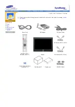
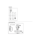
Page 15: ...4 Mounting Bracket 3 Speaker ...

Page 16: ...a DVD Player Connecting a Camcorder Connecting D TV Set Top Box Connecting Speakers Connecting to an Audio System and Sub woofer 1 Connecting to a Computer 1 Connect the power cord to the Adapter and connect the adapter jack to the DC28V power port on the back of your monitor 2 Connect the signal cable to the video port on your computer 3 Connect the audio cable for your monitor to the audio port ...

Page 17: ...amcorders using the Source button on the monitor s front 4 Then start the DVD VCR or Camcorders with a DVD disc or tape inserted 3 Connecting to a DVD Player 1 Connect a set of audio cables between the COMPONENT1 DVD L R AUDIO INPUT jacks on the Monitor and the AUDIO OUT jacks on the DVD player 2 Connect a video cable between the COMPONENT1 DVD Y Pb Pr jacks on the Monitor and the Y Pb Pr jacks on...

Page 18: ...cluded with a Camcorder If not check your local electronics store If your camcorder is stereo you need to connect a set of two cables 5 Connecting D TV Set Top Box The connections for a typical set top box are shown below 1 Connect a set of audio cables between the COMPONENT2 DTV L R AUDIO INPUT jacks on the Monitor and the AUDIO OUT jacks on the Set Top Box 2 Connect a video cable between the COM...

Page 19: ... ends of the cable with the diagram on the Monitor 7 Connecting to an Audio System and Sub woofer 1 Connect a set of audio cables between the AUX L R jacks on the AUDIO SYSTEM and the AUDIO OUTPUT L R jacks on the Monitor 2 Connect an audio cable between the INPUT jack on an active powered Sub woofer and the WOOFER OUT jack on the Monitor ...

Page 20: ...serial cable should be connected between the serial port on a PC and the serial port on a display Figure 1 1 shows how a PC and multiple displays are connected 2 Install 1 PC Requirements recommended Pentium II 64M or greater RAM 800 x 600 256 color or higher PC display 2 OS Windows 95 Windows 98 Windows ME Windows 2000 Windows XP and XP Professional Minimum system requirement for MDC Program Wind...

Page 21: ...is not guaranteed when the user run this program with other models 4 Select a folder to install the program and click the button to begin setup 5 Select a program group and click Continue to continue installation 6 If you see the message Version Conflict as below during installation ignore the message and click Yes because it means that this version is not compatible with the existing program libr...

Page 22: ... to control displays 6 The current title to be controlled is displayed 7 Allows you to enable or disable the remote control signal receiving function of the display unit 8 Indicates the communication status between the LCD and the display Shows Busy while communicating and Idle when the communication is off Note The remote control Enable Disable function operates whether or not the power is On Off...

Page 23: ...etup of your PC 4 Use Exit to end the program The Help menu shows how to use the program and general information about the program 3 Beginning Port Change 1 The Multiple Display Control uses only with Com1 It does not function with any other ports including Com2 2 You can change the port to Com1 in Windows 2000 as follows 3 Go to Control Panel System Hardware Device Manager Ports Right Mouse Click...

Page 24: ... the selected display from the sets and displays it in the slider When you cancel the selection or choose Select All the value returns to the default value 10 3 Mute On Off Turns the mute of the selected display On Off When selecting one set at a time if the selected set is already set to MUTE you must mark the MUTE display If you choose undo the selections or choose Select All the values return t...

Page 25: ...ontrol applies only to the displays for which the current status is ON 6 Aspect Ratio Control Video S Video DVD 1 Click Aspect of the main icons and the Aspect Ratio control screen appears Info Grid shows some basic information necessary to Aspect Ratio Control 1 Power Shows the power status of the current display 2 Aspect Shows the current Aspect Ratio of the display in use 3 Input Source Shows t...

Page 26: ... to control Info Grid shows some basic information necessary to Aspect Ratio Control 1 Click the DTV tab to adjust Aspect Ratio for DTV 2 Info Grid displays only the display having DTV as input source 3 Adjust Aspect Ratio of the selected display one by one 4 You can also adjust Aspect Ratio for Video PC if you click on the Video or the PC tabs Aspect Ratio Control is available only for the displa...

Page 27: ... the displays for which the power status is ON 7 Time Control 1 Click Time of the main icons and the Time Control screen appears Info Grid shows some basic information necessary to Time Control 1 Current Time Set the current time for the selected display PC Time To change the current time first change the PC Time 2 On Time Setup Set the hour minute AM PM of On Time volume of the selected display 3...

Page 28: ...ches to CUSTOM mode automatically 1 Picture Available only for Video S Video DVD and DTV 2 Contrast Adjusts Contrast of the selected display 3 Brightness Adjusts Brightness of the selected display 4 Sharpness Adjusts Sharpness of the selected display 5 Color Adjusts Color of the selected display 6 Tint Adjusts Tint of the selected display Settings Control is available only for the displays for whi...

Page 29: ... for PC Digital 2 Contrast Adjusts Contrast of the selected display 3 Brightness Adjusts Brightness for the selected display 4 Red Gain Adjusts Red Gain of the selected display 5 Green Gain Adjusts Green Gain of the selected display 6 Blue Gain Adjusts Blue Gain for the selected display Settings Control is available only for the displays for which the power status is ON and the default value is 50...

Page 30: ...e Grid 1 Image Lock Controls the Image Lock setting only for PC Analog 2 Frequency Adjusts Frequency of the selected display 3 Phase Adjusts Phase of the selected display 4 Position Adjusts Position of the selected display 5 Auto Adjustment Adjusts the Audio settings of the selected display Settings Control is available only for the displays for which the power status is ON 9 Troubleshooting 1 The...

Page 31: ...ogram in an Irregular manner Rerun the program and turn the remote function again to Restore normal functions 6 Note This program may malfunction due to problems in communication circuits or interference from electronic appliances nearby 7 Go to Samsung Electronics Web Site or contact Samsung Electronics personnel at phone numbers contact info service centers etc additional info necessary 10 Setti...

Page 32: ...e indicator to indicate the currently displayed input signal To switch Screen modes PC Analog PC Digital Video S Video DVD DTV Press here to view Screen Mode Switching Animation Clips 5 Menu button Exit button When screen adjustment menu is off Use this button to open the OSD and activate a highlighted menu item When screen adjustment menu is on Exit button exits from the menu screen or closes scr...

Page 33: ...t temporarily The audio resumes if Mute or VOL button is pressed in the Mute mode 6 P Size button Press to change the screen size 7 Display button Shows a Video Source Audio Source current channel number an audio type and Speaker Mute ON OFF on the upper right corner of the screen 8 P MODE button Adjust the Monitor picture by selecting one of the preset factory settings or select your personal cus...

Page 34: ...ord rewind or fast forward If the button is pressed during Full Automatic play the function will be can celled REW Press to rewind a tape in your VCR PLAY Pause Press the Play Pause button to play back prerecorded tapes or pause the tape FF Press to fast forword the tape in your VCR 19 Swap button Exchanges the video signal that is currently displayed on the main screen with the signal in the PIP ...

Page 35: ...r Adjustment Menu by simply pressing Auto button once Or they are used to adjust monitor functions You need to activate functions other than Auto Adjustment only when Auto Access Features are off 1 Volume When OSD is not on the screen push the or button to adjust volume 1 Push the button to decrease the volume 2 Push the button to increase the volume ...

Page 36: ...e between the left and the right speakers The ideal setting is 50 for the left speaker and 50 for the right speaker ID Assigns individual ID to the SET 1 ID Setup Assigning distinctive IDs to the SET 2 ID Input Use to select the transmitter functions of the individual SET Only the SET whose ID corresponds to the transmitter setting becomes activated Function Funtion Settings 1 Time Clock Setting 2...

Page 37: ...he Red value Green Adjusting the Green value font Blue Adjusting the Blue value Image recall Initializing the Display Settings Color recall Initializing the Color Settings 2 PC Digital Screen For detailed information on Screen Adjustment in the PC Digital mode refer to PC Digital Screen Adjustment Animation Clips Sound For explanations on the PC Digital control menu refer to the explanations under...

Page 38: ...nce between the left and the right speakers The ideal setting is 50 for the left speaker and 50 for the right speaker ID For explanations on the PC Digital control menu refer to the explanations under Video Screen You may control Monitor properties in the same way as for PC Analog Screen Function Funtion Settings 1 Time Clock Setting 2 PIP When external A V devices such as VCR or DVD are connected...

Page 39: ...osition Adjusting Vertical Size Sound For explanations on the DVD DTV control menu refer to the explanations under Video Screen You may control Monitor properties in the same way as for Video S Video Screen ID For explanations on the PC Digital control menu refer to the explanations under Video Screen You may control Monitor properties in the same way as for PC Analog Screen Function Funtion Setti...

Page 40: ... becomes disconnected or damaged 4 Turn off your monitor and reconnect the video cable then turn on both your computer and the monitor If your monitor screen remains blank after using the previous procedure check your video controller and computer system your monitor is functioning properly Video mode not supported This indicates the display resolution or refresh rate is not properly set on your c...

Page 41: ...ity by selecting resolution depending on the monitor screen size as follows 40 inch monitor 1280 x 768 60Hz Select 16 or 24 bit color Supported or not subject to the video card the monitor is irrelevant LCD monitors may display up to 16 77 million colors 24 bits Dot Acceptable TFT LCD panel manufactured by using advanced semiconductor technology with precision of 99 999 above is used for this prod...

Page 42: ...lems Solutions Screen is blank and power indicator is off z Ensure that the power cord is firmly connected and the LCD monitor is on Refer to the Connecting Your Monitor Check Signal Cable message z Ensure that the signal cable is firmly connected to the PC or video sources Refer to the Connecting Your Monitor z Ensure that the PC or video sources are turned on Video mode not supported message z C...

Page 43: ...el Refer to the Volume Sound level is too low z Check the volume level Refer to the Volume z If the volume is still too low after turning the control to its maximum check the volume control on the computer sound card or software program Sound is too high pitched or too low pitched z Adjust the Treble and Bass to appropriate level 4 Problems related to Remote Control Problems related to the remote ...

Page 44: ...ings Windows ME 2000 Set the resolution at the Control Panel Display Settings Contact the video card manufacturer for details How can I set the Power Saving function Windows XP Reset Power Saving parameters by clicking Control Panel Appearance Theme Display Screen Saver or in the computer BIOS SETUP Refer to Windows Computer Manual Windows ME 2000 Set the function at BIOS SETUP of the computer or ...

Page 45: ...ay Color 16 777 216 Colors Resolution Optimum resolution 1024 x 768 60Hz Maximum resolution 1280 x 768 60Hz Input Signal Sync Separate TTL P or N Composite TTL P or N Video signal 0 7 Vp p 75 ohm Video Color system NTSC Sound system M N Video format CVBS S VHS RGB DVD YPbPr 480i Only component 1 480P 720P 1080i DTV YPbPr 480P 720P 1080i Maximum Pixel Clock 90 MHz Power Supply AC 90 264 V 1 0 0 5A ...

Page 46: ... can be installed on any Plug Play compatible system Interaction of the monitor and computer systems will provide the best operating conditions and monitor settings In most cases monitor installation will proceed automatically unless the user wishes to select alternate settings Dot Acceptable TFT LCD panel manufactured by using advanced semiconductor technology with precision of 99 999 above is us...

Page 47: ...ended for long periods The PowerSaver system operates with a VESA DPMS compliant video card installed in your computer Use a software utility installed on your computer to set up this feature State Normal Operation Power saving mode EPA ENERGY 2000 Power Switch off Power Indicator Green Green Blinking Amber Power Consumption Less than 230W Less than 8W Less than 1W This monitor is EPA ENERGY STAR ...

Page 48: ... 480 37 861 72 809 31 500 VESA 640 x 480 37 500 75 000 31 500 VESA 800 x 600 37 879 60 317 40 000 VESA 800 x 600 48 077 72 188 50 000 VESA 800 x 600 46 875 75 000 49 500 VESA 1024 x 768 48 363 60 004 65 000 VESA 1024 x 768 56 476 70 069 75 000 VESA 1024 x 768 60 023 75 029 78 750 GTF 1280 x 768 47 700 60 000 80 136 Horizontal Frequency The time to scan one line connecting the right edge to the lef...

Page 49: ...Cra 9 No 99A 02 Of 106 Bogota Colombia Tel 9 800 112 112 Fax 571 618 2068 http www samsung latin com e mail soporte samsung latin com PANAMA Samsung Electronics Latinoamerica Z L S A Calle 50 Edificio Plaza Credicorp Planta Baja Panama Tel 507 210 1122 210 1133 Tel 800 3278 FAST http www samsung latin com PERU Servicio Integral Samsung Av Argentina 1790 Lima1 Peru Tel 51 1 336 8686 Fax 51 1 336 85...

Page 50: ...ll free 8 800 502 0000 SWEDEN DENMARK NORWAY FINLAND Samsung Electronics AB Box 713 S 194 27 UPPLANDS VÄSBY SVERIGE Besöksadress Johanneslundsvägen 4 Samsung support Sverige 020 46 46 46 Samsung support Danmark 8088 4646 Samsung support Norge 8001 1800 Samsung support Finland 0800 118001 Tel 46 8 590 966 00 Fax 46 8 590 966 50 http www samsung se HUNGARY Samsung Electronics Magyar Rt 1039 Budapest...

Page 51: ...TRIAL VALLEJO DEL GUSTAVO A MADERO C P 07700 MEXICO D F TEL 5747 5100 RFC SEM950215S98 EXPORTADO POR SAMSUNG ELECTRONICS CO LTD JOONG ANG DAILY NEWS BLDG 7 SOON WHA DONG CHUNG KU C P O BOX 2775 1144 SEOUL KOREA CHILE SONDA S A Teatinos 550 Santiago Centro Santiago Chile Fono 56 2 5605000 Fax 56 2 5605353 56 2 800200211 NETHERLANDS BELGIUM LUXEMBOURG Samsung Electronics Benelux B V Fleminglaan 12 2...

Page 52: ...Hz Example If the same light repeats itself 60 times per second this is regarded as 60 Hz In this case flickering of the screen can be detected To avoid this problem there is a Flicker free Mode using a vertical frequency over 70 Hz Horizontal Frequency The time to scan one line connecting the right edge to the left edge of the screen horizontally is called Horizontal Cycle The inverse number of t...

Page 53: ...uipment If necessary consult your dealer or an experienced radio television technician for additional suggestions You may find the booklet called How to Identify and Resolve Radio TV Interference Problems helpful This booklet was prepared by the Federal Communications Commission It is available from the U S Government Printing Office Washington DC 20402 Stock Number 004 000 00345 4 The party respo...

Page 54: ...ity to the following European Norms z EN55022 1998 Radio Frequency Interference z EN55024 1998 Electromagnetic Immunity z EN61000 3 2 1995 A1 A2 Power Line Harmonics z EN61000 3 3 1995 Voltage Fluctuations z EN60950 Product Safety PCT Notice VCCI This is a Class B product based on the standard of the Voluntary Control Council for Interference by Information Technology Equipment VCCI If this is use...

Page 55: ... the printed or scanned images For more information refer to Help F1 in the software program How to install the Natural Color software Insert the CD included with the Samsung monitor into the CD ROM Drive Then the initial screen of the program installation will be executed Click Natural Color on the initial screen to install the Natural Color software To install the program manually insert the CD ...

Page 56: ...ction with the furnishing performance or use of this material Samsung is the registered trademark of Samsung Electronics Co Ltd Microsoft Windows and Windows NT are registered trademarks of Microsoft Corporation VESA DPMS and DDC are registered trademarks of Video Electronics Standard Association the ENERGY STAR name and logo are registered trademarks of the U S Environmental Protection Agency EPA...

Page 57: ...http www samsung monitor com Worldwide http www samsungusa com monitor USA http www sec co kr monitor Korea http www samsungmonitor com cn China ...

Reviews: