

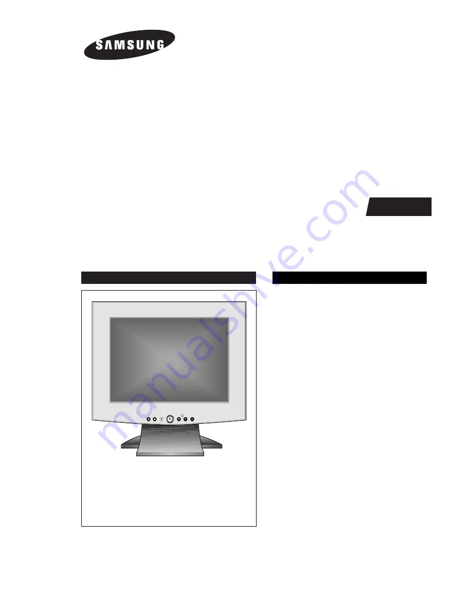
COLOR MONITOR
SyncMaster 570BTFT
SyncMaster 580BTFT
(RN15MSS / RN15MST
RN15MOS / RN15MOT)
Manual
SERVICE
COLOR MONITOR
CONTENTS
EXIT
MENU
AUTO
EXIT
MENU
AUTO
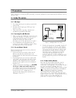
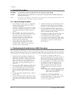
1. Precautions
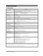
2. Product Specifications
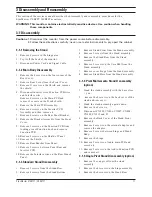
3. Disassembly & Reassembly
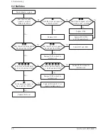
4. Troubleshooting
5. Exploded View & Parts List
6. Electrical Parts List
7. Block Diagram
8. Wiring Diagram
9. Schematic Diagrams
Summary of Contents for SyncMaster 570B TFT
Page 10: ...3 Disassembly and Reassembly SyncMaster 570BTFT 580BTFT 3 3 ...
Page 13: ...Memo 3 Disassembly and Reassembly 3 6 SyncMaster 570BTFT 580BTFT ...
Page 20: ...5 Exploded View Parts List 5 2 Multimedia Pivot base RN15MST TOSHIBA PANEL ...
Page 21: ...5 Exploded View Parts List 5 4 Multimedia base RN15MST TOSHIBA PANEL ...
Page 22: ...5 Exploded View Parts List 5 6 Pivot base RN15MST TOSHIBA PANEL ...
Page 23: ...5 Exploded View Parts List 5 8 Simple base RN15MST TOSHIBA PANEL ...
Page 24: ...5 Exploded View Parts List 5 10 Wire frame base RN15MST TOSHIBA PANEL ...
Page 36: ...6 Electrical Parts List 6 12 SyncMaster 570BTFT 580BTFT Memo ...
Page 38: ...Memo 7 Block Diagrams 7 2 SyncMaster 570BTFT 580BTFT ...
Page 40: ...SyncMaster 570BTFT 580BTFT ...
Page 41: ...9 2 ...
Page 42: ...SyncMaster 570BTFT 580BTFT ...
Page 43: ...9 4 ...
Page 45: ...5 1 SyncMaster 570STFT 580STFT 5 Exploded View and Parts List 5 1 Simple base 570STFT ...
Page 46: ...5 2 MultiMedia base 570STFT 5 Exploded View Parts List SyncMaster 570STFT 580STFT 5 2 ...
Page 47: ...10 Schematic Diagrams 5 3 SyncMaster 570STFT 580STFT 5 3 Pivot MultiMedia base 570STFT ...
Page 48: ...5 Exploded View Parts List SyncMaster 570STFT 580STFT 5 4 5 4 Angle Pivot base 570STFT ...
Page 49: ...10 Schematic Diagrams 5 5 SyncMaster 570STFT 580STFT 5 5 Wire frame base 570STFT ...
Page 50: ...5 6 Simple base 580STFT 5 Exploded View Parts List SyncMaster 570STFT 580STFT 5 6 ...
Page 51: ...10 Schematic Diagrams 5 7 SyncMaster 570STFT 580STFT 5 7 MultiMedia base 580STFT ...
Page 52: ...5 8 Pivot MultiMedia base 580STFT 5 Exploded View Parts List SyncMaster 570STFT 580STFT 5 8 ...
Page 53: ...5 9 Angle Pivot base 580STFT 10 Schematic Diagrams 5 9 SyncMaster 570STFT 580STFT ...
Page 54: ...5 10 Wire frame base 580STFT 5 Exploded View Parts List SyncMaster 570STFT 580STFT 5 10 ...
Page 55: ...9 1 SyncMaster 570STFT 580STFT 9 Schematic Diagrams 9 1 DAC IO Part Schematic Diagram 5 7 6 ...
Page 60: ...Samsung Electronics Co Ltd September 1999 Printed in Korea Code No BN68 00084A ...


