background image


3


Français

Español

Deutsch

Italiano

English

Portuguese


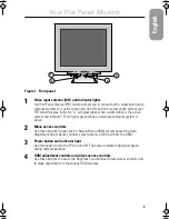
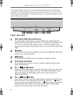
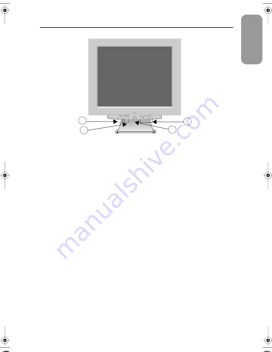
Figure 1.  Front panel


1


Video input selector (A/B) and indicator lights


Your Flat Panel Display (FPD) monitor allows you to connect both a workstation and a 
computer system to it at the same time. Use this button to select which system your 
FPD should display. Indicator “A” will glow green when a workstation is the active 
system and indicator “B” will glow green when an alternate computer system is 
active.


2


Menu access controls


Use these buttons to open the On-Screen Menu (OSM) system access the Auto 
Adjustment Direct-Access Control, select a menu, and to exit from the OSM.


3


Power button and indicator light


Use this button to turn the FPD on and off. The power indicator light glows green 
during normal operation.


4


OSM adjustment controls and direct-access controls


Use these buttons to access the Brightness and Contrast Direct-Access controls and 
to make adjustments to the various OSM features.

4

3

1

2


Your Flat Panel Monitor


sa800e2.fm  Page 3  Monday, May 29, 2000  2:09 PM

Summary of Contents for SyncMaster 800TFT

Page 1: ...SyncMaster 800TFT TFT LCD Monitor Owner s Instructions ...

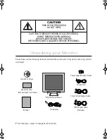
Page 2: ...itor CAUTION RISK OF ELECTRIC SHOCK DO NOT OPEN CAUTION TO REDUCE THE RISK OF ELECTRIC SHOCK DO NOT REMOVE COVER OR BACK NO USER SERVICEABLE PARTS INSIDE REFER SERVICING TO QUALIFIED SERVICE PERSONNEL Manual Warranty Card Colorific Driver 13W3 Signal Cable Optional Power Cord Monitor and Stand 15 pin D Sub Signal Cable Power adapter Cable Holder DC Adapter Not available in all areas ...

Page 3: ...Test Feature Check STFC 7 Adjusting Your FPD 8 Automatic Save 9 Direct Access Features 9 OSM Lock Unlock 10 Menu System 11 Accessing the Menu System 11 PowerSaver 15 Troubleshooting 16 Appendix 18 Specifications 18 Pin Assignments 19 Display Modes 20 Changing the Stand 21 Removing the Stand 21 Attaching an Arm Type Stand or Wall Mount Hanger 21 Index Index 1 Regulatory Information Inside back cove...

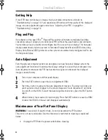
Page 4: ...ed space be sure to provide adequate ventilation 7 Put your FPD in a location with low humidity and a minimum of dust 8 Do not expose the FPD to rain or use it near water In kitchens near swimming pools etc If the FPD accidentally gets wet unplug it and contact an authorized dealer immediately You can clean the FPD with a damp cloth when necessary but be sure to unplug the FPD first 9 Place the FP...

Page 5: ...tor B will glow green when an alternate computer system is active 2 Menu access controls Use these buttons to open the On Screen Menu OSM system access the Auto Adjustment Direct Access Control select a menu and to exit from the OSM 3 Power button and indicator light Use this button to turn the FPD on and off The power indicator light glows green during normal operation 4 OSM adjustment controls a...

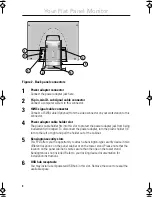
Page 6: ...disconnect the power adapter turn the plastic holder 1 4 turn to the left or right and pull the holder out of the cabinet 5 Kensington security slots This FPD offers you the opportunity to attach a Kensington type security device in two different locations on the panel cabinet or on the tower stand Please note that the location on the panel cabinet is more secure than the one on the tower stand Ke...

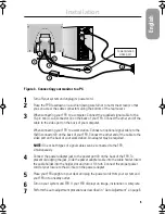
Page 7: ... FPD Connect the other end of the cable to the video port on the back of your workstation An adapter may be required NOTE One or both types of signal cables can be connected to the FPD simultaneously 4 Connect the power adapter jack to the power port on the back of the FPD To prevent dislodging the jack slide the power adapter cable into the cable holder Insert the cable holder into the holder slo...

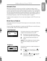
Page 8: ...ystem can recognize your new flat panel display system the auto adjustment function will optimize the display settings for use with your computer Use Auto Adjustment whenever the FPD has become misaligned or whenever the displayed image is unsatisfactory 1 Turn on your computer and flat panel display 2 Push the EXIT button to open the Auto Adjustment OSM 3 Push the button to activate the Auto Adju...

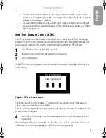
Page 9: ...r is lit use the following steps to perform the FPD self test 1 Turn off both your computer and the monitor 2 Unplug the video cable from the computer or video card 3 Turn on the monitor If the FPD is functioning properly you will see a white box with a red border and black text inside stating Figure 4 FPD self test screen The three boxes inside the border are red green and blue Failure of any of ...

Page 10: ...en menu OSM exits from menus and sub menus and exits the OSM 3 MENU button This button opens the OSM system and activates the highlighted function 4 Power button and indicator Use this button to turn the FPD on and off The power indicator light glows green during normal operation 5 The and buttons When used with the OSM system these buttons allow you to select sub menu items and to move the select...

Page 11: ...ribed on this page and the next page can be accessed quickly at the touch of one button Once you finish making adjustments to a feature push the EXIT button to turn off the menu or allow the OSM to time out and disappear automatically Auto Adjustment Follow these instructions to enable or disable the automatic screen adjustments for your FPD 1 With the menu off push the EXIT button The automatic a...

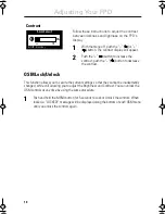
Page 12: ...button for 5 seconds to Lock or Unlock the controls When locked a LOCKED message will be displayed along the bottom of each OSM menu until you unlock the controls again Contrast Follow these instructions to adjust the contrast between darkness and lightness on the FPD s display 1 With the menu off push the or button The contrast display will appear 2 Push the button to increase the contrast push t...

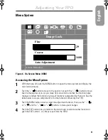
Page 13: ... icon to another the function name changes to reflect the function or group of functions represented by that icon See the table below to view a complete list of all the functions offered by this FPD 3 Push the MENU button once to select the adjustment function then use the or and the or buttons to make your changes 4 Push the EXIT button once to return to the main menu to select another function o...

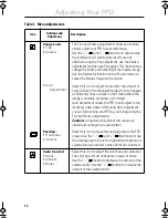
Page 14: ... lines or areas on the screen where the image is unstable and jitters or shimmers Auto Adjustment allows the FPD to self adjust to the incoming video signal After using Auto Adjustment you can further tune your FPD to your liking using the Fine and Coarse adjustments Caution Using Auto Adjustment will cause any stored user settings to be overwritten Position Horizontal Vertical Select this icon to...

Page 15: ...ime sets the length of time the OSM will remain active after the last time you pushed a button The default time is 10 seconds Menu Position Vertical Horizontal Select this icon to change the position of the OSM on the screen The and buttons move the OSM Select the Horizontal function to move the OSM to the left or right select the Vertical function to move the OSM up or down Image Size Normal Expa...

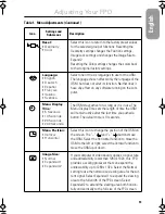
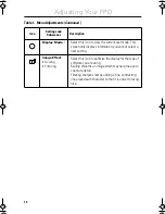
Page 16: ...ing Select this icon to optimize the display for the type of software you are using Scaling smooths an image which may help the eye to see more detail Filtering sharpens text by adding a fine contrasting line around each character so that it is easier to recog nize Table 1 Menu Adjustments Continued Icon Settings and Sub menus Description i Adjusting Your FPD ...

Page 17: ...nservation turn your monitor OFF when it is not needed or when leaving it unattended for long periods NOTE Screen saver video patterns designed for use with CRT based monitors are not recom mended for use with your FPD since they may not extinguish the FPD s back light resulting in premature aging State Normal Operation Power Saving Function mode EPA NUTEK Standby Mode Sleep Mode Position A1 Deep ...

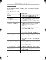
Page 18: ...in the preset timing modes page 20 Picture is scrambled Check the signal cable connection between the computer and FPD Perform Auto Adjustment see page 6 Picture is not clear Adjust Fine and Coarse adjustments as needed see page 12 Picture is fuzzy Perform FPD reset Eliminate accessories i e video extension cables Picture bounces or has wavy oscillations Check the signal cable connection between t...

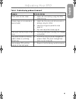
Page 19: ...page 13 Run Auto Adjustment see page 6 The power indicator blinks amber once The flat panel display is saving your changes to the OSM The power indicator is blinking green amber or is blinking amber only The FPD is using its power management system Check the power management utility on your computer Cannot adjust FPD with the buttons on the front panel Please contact Samsung customer service Table...

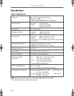
Page 20: ...0 7 Vpp positive at 75 W Separate sync composite and sync on green Maximum Pixel Clock 135 MHz Power Adapter AC 90 264 Volt 60 Hz 50 Hz 3 Hz Power Consumption 60 W Maximum 56 W Nominal Dimensions Weight W x D x H Unit 449 4 x 461 2 x 182 0 mm 9 35 kg 17 7 x 18 2 x 7 2 in 20 61 lb Carton 570 x 295 x 580 mm 12 8 kg 22 4 x 11 6 x 22 8 in 28 22 lb All measurements approximate VESA Mounting Interface 1...

Page 21: ...Data H Sync V Sync DDC Clock Red Green Blue GND GND DDC Return GND R GND G GND B NC GND Sync Self test GND DDC Data H Sync V Sync DDC Clock Table 6 13W3 Connector Pin No 13W3 Side of the Signal Cable Composite H V A1 A2 A3 1 2 3 4 5 6 7 8 9 10 Red video signal Green video signal Blue video signal SCL NC S2 S gnd H Sync SDA V Sync S1 S0 Sync Return Red video signal Green video signal Blue video sig...

Page 22: ... display modes listed below the screen image has been optimized during manufacture Table 7 Preset timing modes Display Mode Horizontal Frequency kHz Vertical Frequency Hz Pixel Clock MHz Sync Polarity H V 720 x 400 31 469 70 087 28 322 640 x 480 31 469 59 940 25 175 640 x 480 37 500 75 000 31 500 640 x 480 43 269 85 008 36 000 800 x 600 46 875 75 000 49 500 800 x 600 53 674 85 061 56 250 1024 x 76...

Page 23: ...otect the screen 3 Remove the four screws securing the stand and remove it Attaching an Arm Type Stand or Wall Mount Hanger NOTE This monitor accepts a 100mm x 100mm VESA compliant mounting interface pad 1 Align the Mounting Interface Pad with the holes in the Rear Cover and secure it with the four screws that came with the Arm type Stand or Wall Mount Hanger 14V DC 14V DC B B A A Rear cover Mount...

Page 24: ...ling 14 Image lock 12 Auto adjustment 12 Coarse 12 Fine 12 Image size 13 Expanded 1 13 Expanded 2 13 Normal 13 Italiano 13 K Kensington security slots 4 L Language 13 Deutsch 13 English 13 Español 13 Français 13 Italiano 13 M Menu display time 13 Menu position 13 Horizontal 13 Vertical 13 N No Connection Check Signal Cable 16 Normal 13 R Red 12 Reset 13 Color 13 Geometry 13 S Safety instructions 2...

Page 25: ...ce for the product Declaration of conformity for products Marked with FCC Logo This device complies with Part 15 of the FCC Rules Oper ation is subject to the following two conditions 1 this device may not cause harmful interference and 2 this device must accept any interference received including interference that may cause undesired operation The party responsible for product compliance SAMSUNG ...

Page 26: ...sung Electronics UK Ltd Samsung House 225 Hook Rise South Surbiton Surrey KT6 7LD Tel 0181 391 0168 Fax 0181 397 9949 European Service Center National Service Stafford Park 12 Telford Shropshire TF3 3BJ Tel 01952 292 262 Fax 01952 292 033 THAILAND Samsung Service Center 729 729 1 JSP Tower Rachadapisek RD Bangpongpang Yannawa Bangkok 10120 Tel 662 2954508 14 Fax 662 2954267 SOUTH AFRICA Samsung El...

Reviews: