Alignments and Adjustments (Mechanical)
Samsung Electronics
4-9
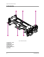
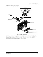
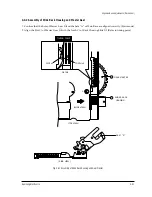
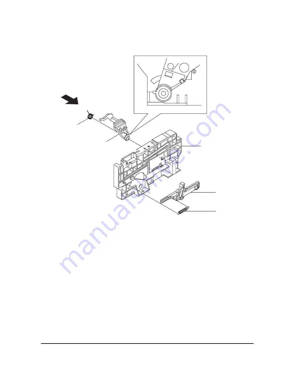
4-2-5 Chassis Side “R” Parts Locations
CHASSIS SIDE "R"
(SIDE VIEW "A")
SLIDE DAMPER
LEVER-LID OPENDER
"A"
SPRING-SLIDE DAMPER
SPRING-LID OPENDER
Fig. 4-9 Chassis Side “R” Parts Locations
Note
:
If you operate the deck when the Cassette AssÕy Holder is removed, the Arm Shaft ÒRÓ and the
Damper Slide are not returned to their original positions. If this happens by accident, push the Damper
Slide of Side Chassis ÒRÓ in the direction of arrow ÒDÓ, and return the Damper Slide in the reverse
direction of arrow ÒDÓ when the Arm Shaft AssÕy is in eject mode.
Summary of Contents for TB531VCT1X/XSA
Page 2: ...ELECTRONICS Samsung Electronics Co Ltd NOV 1998 Printed in Korea 3SCV11F 3115 ...
Page 8: ...MEMO 2 2 Samsung Electronics ...
Page 144: ...Wiring Diagram 11 2 Samsung Electronics 11 2 SCV11F Wiring Diagram ...
Page 146: ...Schematic Diagrams 12 2 Samsung Electronics 12 2 VCR SYSTEM BLOCK 4 3 1 5 2 6 ...
Page 148: ...Schematic Diagrams 12 4 Samsung Electronics 12 4 VCR POWER BLOCK ...
Page 149: ...Schematic Diagrams 12 5 Samsung Electronics 12 5 TV 1 4 RED POWER LINE BLUE SIGNAL LINE ...
Page 151: ...Schematic Diagrams 12 7 Samsung Electronics 12 7 TV 3 4 RED POWER LINE BLUE SIGNAL LINE ...

