Alignments and Adjustments (Mechanical)
Samsung Electronics
4-21
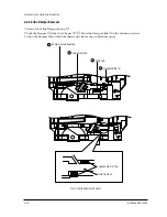
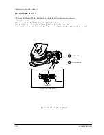
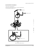
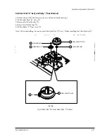
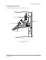
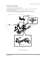
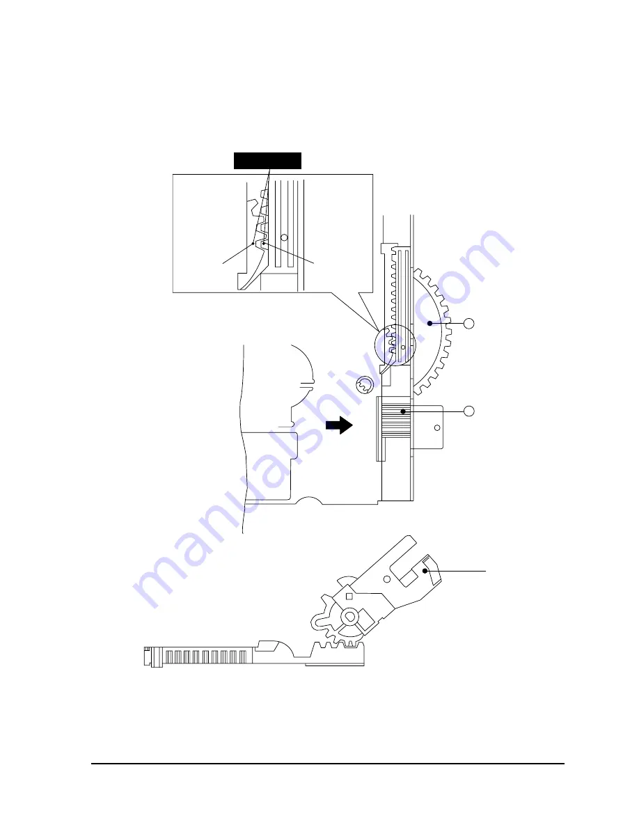
4-4-2 Assembly of Slide Rack Housing and Master Gear
1. Confirm that the hole of Master Gear
①
and the hole ÒAÓ of Main Base are aligned correctly. (Eject mode)
2. Align the Slot #1 of Master Gear
①
with the Tooth #1 of Rack Housing Slide
➁
. (Refer to timing point)
(SLIDE VIEW)
DETAIL
A
TIMING POINT
SLOT #1
TOOTH #1
GEAR MASTER
( TOP VIEW )
( SIDE VIEW )
1
SLIDER RACK
HOUSING
ARM " R"
2
Fig. 4-21 Assembly of Slide Rack Housing and Gear Master
Summary of Contents for TB531VCT1X/XSA
Page 2: ...ELECTRONICS Samsung Electronics Co Ltd NOV 1998 Printed in Korea 3SCV11F 3115 ...
Page 8: ...MEMO 2 2 Samsung Electronics ...
Page 144: ...Wiring Diagram 11 2 Samsung Electronics 11 2 SCV11F Wiring Diagram ...
Page 146: ...Schematic Diagrams 12 2 Samsung Electronics 12 2 VCR SYSTEM BLOCK 4 3 1 5 2 6 ...
Page 148: ...Schematic Diagrams 12 4 Samsung Electronics 12 4 VCR POWER BLOCK ...
Page 149: ...Schematic Diagrams 12 5 Samsung Electronics 12 5 TV 1 4 RED POWER LINE BLUE SIGNAL LINE ...
Page 151: ...Schematic Diagrams 12 7 Samsung Electronics 12 7 TV 3 4 RED POWER LINE BLUE SIGNAL LINE ...

