Alignments and Adjustments (Mechanical)
4-26
Samsung Electronics
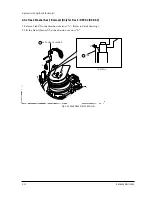
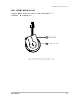
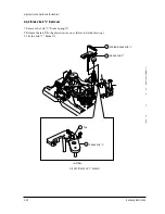
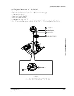
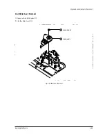
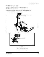
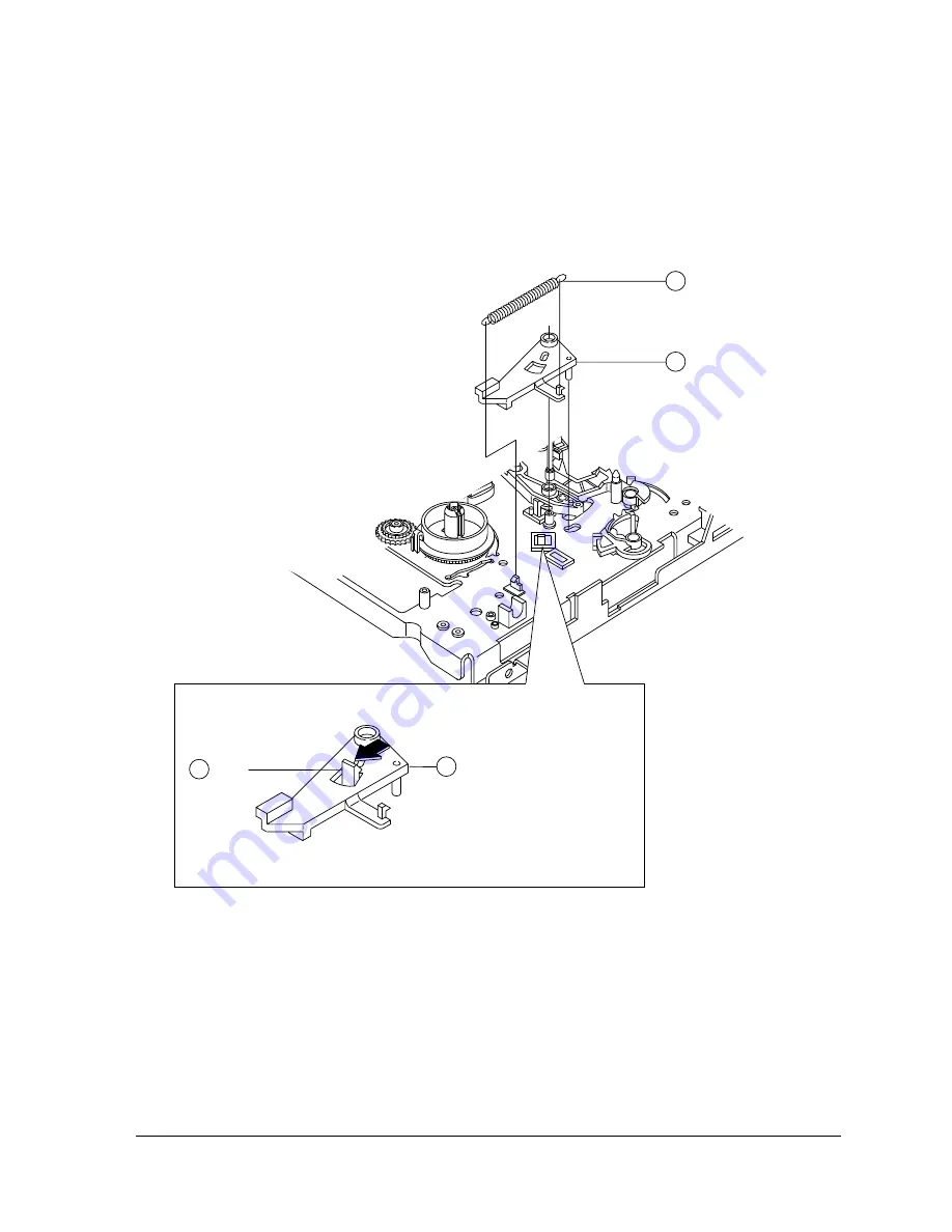
4-4-7 Sub Brake “R” Ass’y Removal
1. Remove the Sub ÒRÓ Brake Spring
①
.
2. Release the tab
➁
in the direction of arrow. (Refer to detail drawing)
3. Lift the Brake Sub ÒRÓ AssÕy
➂
.
SPRING-SUB BRAKE "R"
1
SUB-BRAKE "R" ASS'Y
3
SUB-BRAKE "R" ASS'Y
<DETAIL>
3
TAB
2
Fig. 4-26 Sub Brake “R” Ass’y Removal
Summary of Contents for TB531VCT1X/XSA
Page 2: ...ELECTRONICS Samsung Electronics Co Ltd NOV 1998 Printed in Korea 3SCV11F 3115 ...
Page 8: ...MEMO 2 2 Samsung Electronics ...
Page 144: ...Wiring Diagram 11 2 Samsung Electronics 11 2 SCV11F Wiring Diagram ...
Page 146: ...Schematic Diagrams 12 2 Samsung Electronics 12 2 VCR SYSTEM BLOCK 4 3 1 5 2 6 ...
Page 148: ...Schematic Diagrams 12 4 Samsung Electronics 12 4 VCR POWER BLOCK ...
Page 149: ...Schematic Diagrams 12 5 Samsung Electronics 12 5 TV 1 4 RED POWER LINE BLUE SIGNAL LINE ...
Page 151: ...Schematic Diagrams 12 7 Samsung Electronics 12 7 TV 3 4 RED POWER LINE BLUE SIGNAL LINE ...

