Alignments and Adjustments (Mechanical)
4-68
Samsung Electronics
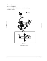
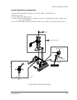
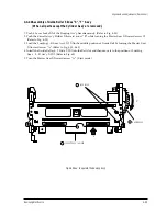
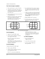
6. Play back the Mono Scope alignment tape (SP mode).
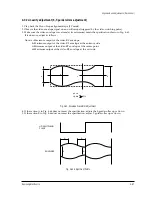
7. Connect an oscilloscope CH-1 to the Envelope and CH-2 to the HÕD SW Pulse for triggering.
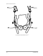
8. Turn the guide roller heads with a flat head ( ) driver to obtain a flat video RF envelope as shown in
Fig. 4-67.
9. After the adjustment is completed, tighten the set screws.
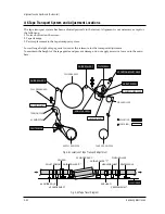
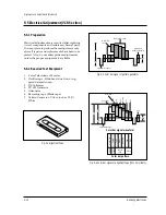
IDEAL ENVELOPE
L HEIGHT
TOO HIGH
GUIDE ROLLER (L)
GUIDE ROLLER (R)
L HEIGHT
TOO LOW
R HEIGHT
TOO LOW
R HEIGHT
TOO HIGH
Fig. 4-67 S, T-Guide Roller Height Adjustment
Summary of Contents for TB531VCT1X/XSA
Page 2: ...ELECTRONICS Samsung Electronics Co Ltd NOV 1998 Printed in Korea 3SCV11F 3115 ...
Page 8: ...MEMO 2 2 Samsung Electronics ...
Page 144: ...Wiring Diagram 11 2 Samsung Electronics 11 2 SCV11F Wiring Diagram ...
Page 146: ...Schematic Diagrams 12 2 Samsung Electronics 12 2 VCR SYSTEM BLOCK 4 3 1 5 2 6 ...
Page 148: ...Schematic Diagrams 12 4 Samsung Electronics 12 4 VCR POWER BLOCK ...
Page 149: ...Schematic Diagrams 12 5 Samsung Electronics 12 5 TV 1 4 RED POWER LINE BLUE SIGNAL LINE ...
Page 151: ...Schematic Diagrams 12 7 Samsung Electronics 12 7 TV 3 4 RED POWER LINE BLUE SIGNAL LINE ...

