3-10
Samsung Electronics
Disassembly and Reassembly
Œ
DISK S REEL
´
DISK T REEL
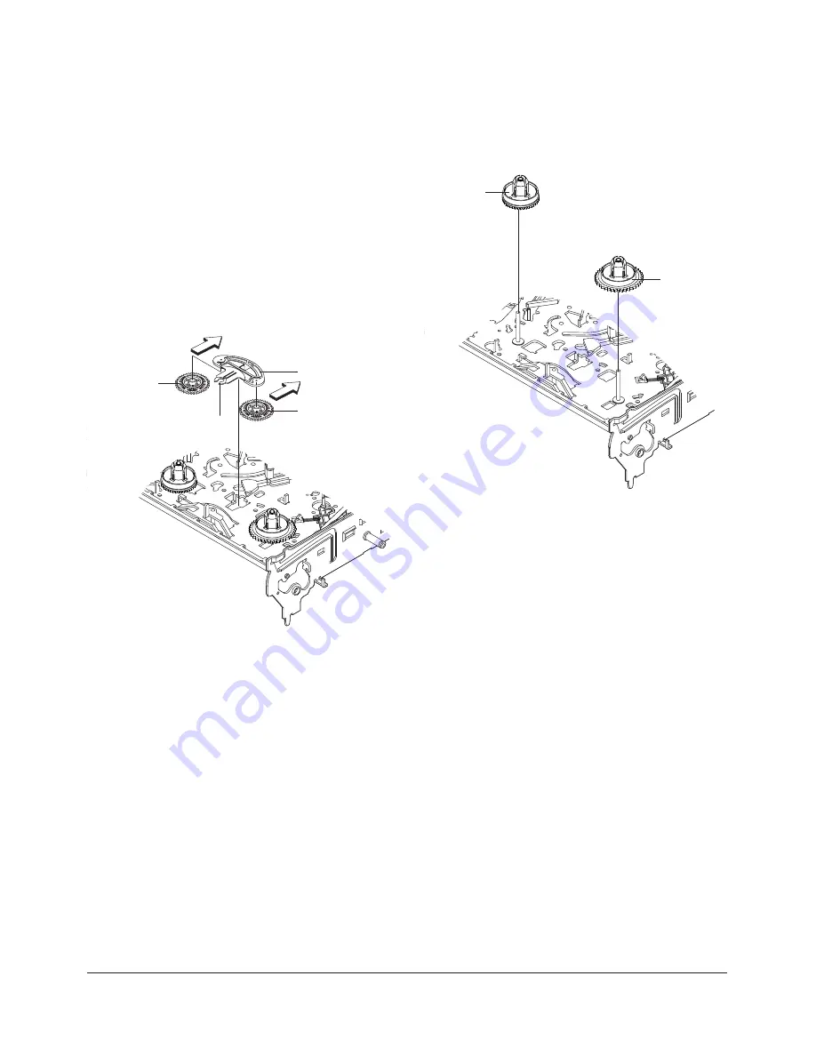
Fig. 3-19 Disk S, T Reel Removal
3-2-13 Gear Idle Ass’y Removal
1) Push the Lever Idle
Œ
in the direction of arrow
“A”, “B”.
2) Lift the Lever Idle
Œ
.
Assembly
:
1) Apply oil in two Bosses of Lever Idle
Œ
.
2) Assemble the Gear Idle
´
with the Lever Idle
Œ
.
Note
: When replacing the Gear Idle
´
, be sure to
add oil in the boss of Lever Idle
Œ
.
3-2-14 Disk S, T Reel Removal
1) Lift the Disk S, T Reel
Œ
,
´
.
´
GEAR IDLE
´
GEAR IDLE
Œ
LEVER IDLE
"A"
HOOK "C"
"B"
Fig. 3-18 Gear Idle Ass’y Removal
Summary of Contents for TI21B4DF4X
Page 98: ...Block Diagrams 8 2 Samsung Electronics 8 2 C17A PCB Layout ...
Page 99: ...9 Wiring Diagram 9 1 C17A Wiring Diagram Wiring Diagram Samsung Electronics 9 1 ...
Page 101: ...Schematic Diagrams 10 2 Samsung Electronics 10 2 MAIN2 VOC TUNER BOX ...
Page 103: ...Schematic Diagrams 10 4 Samsung Electronics 10 4 MAIN4 SWITCHING BLOCK ...
Page 104: ...Schematic Diagrams 10 5 Samsung Electronics 10 5 MAIN5 OPTION PAL HIFI BLOCK ...
Page 105: ...Schematic Diagrams 10 6 Samsung Electronics 10 6 MAIN6 OPTION VCR SECAM BLOCK ...
Page 106: ...Schematic Diagrams 10 7 Samsung Electronics 10 7 POWER FBT ...
Page 107: ...Schematic Diagrams 10 8 Samsung Electronics 10 8 CRT ...
Page 108: ...Schematic Diagrams 10 9 Samsung Electronics 10 9 FRONT A V MASTER SW FRONT A V MASTER SW ...


