Alignments and Adjustments (Mechanical)
Samsung Electronics
4-5
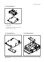
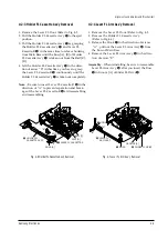
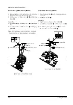
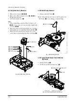
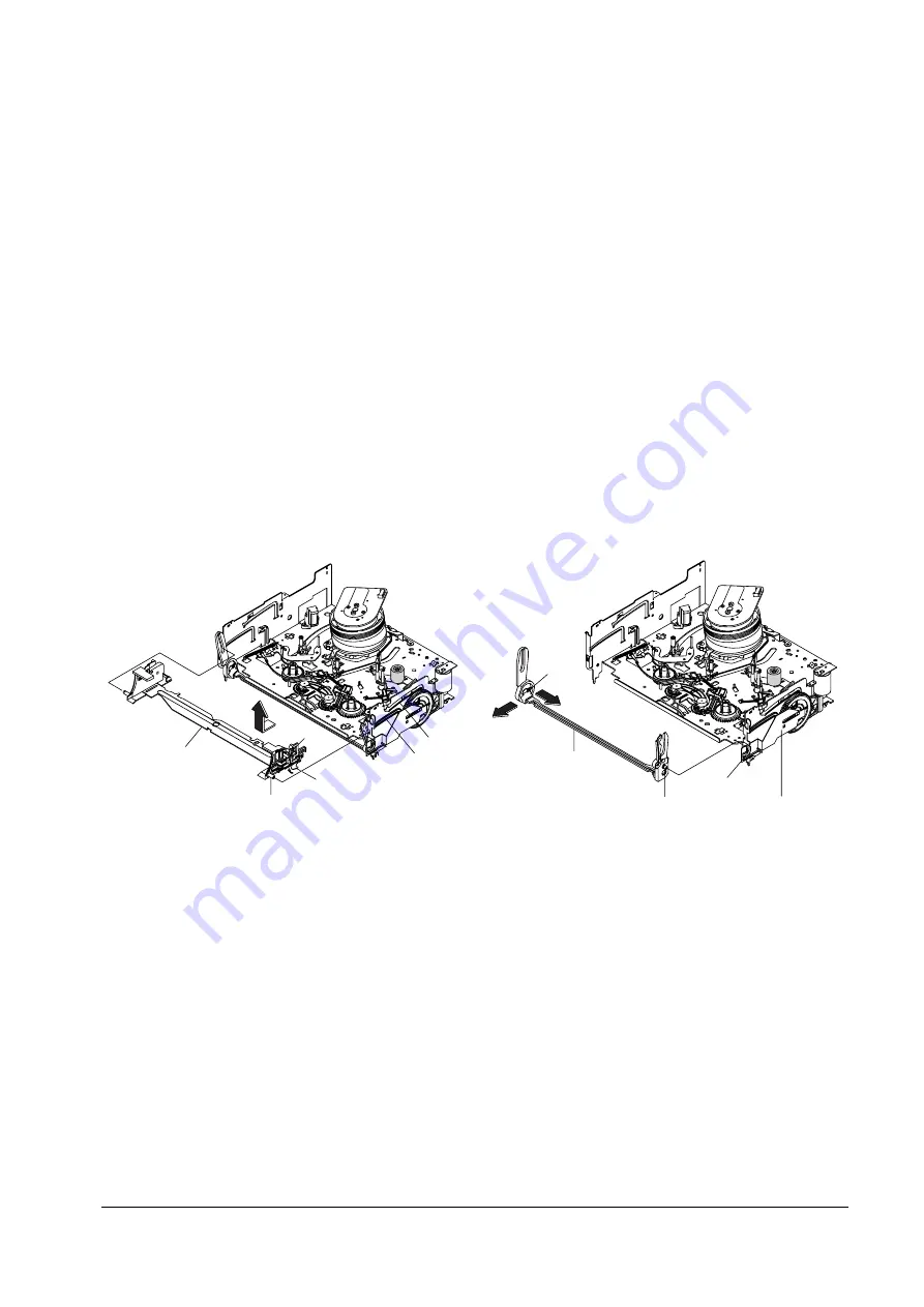
4-2-3 Holder FL Cassette Ass’y Removal
1. Remove the Lever FL Door. (Refer to Fig. 4-5
2. Pull the Holder FL Cassette AssÕy
Œ
to the eject
position.
3. Pull the Holder FL Cassette AssÕy
Œ
as grasping
the Holder FL Cassette AssÕy
Œ
and Lever FL
Cassette-R
´
in the same time to release hooking
from Main Base until the Boss [A], [B] of Holder
FL Cassette AssÕy
Œ
is taken out from the Rail [C],
[D].
4. Lift the Holder FL Cassette AssÕy
Œ
in the direc-
tion of arrow ÒBÓ in this time, you have to grasp
the Lever FL Cassette-R
´
continuously until the
Holder FL Cassette AssÕy
Œ
is taken out completely.
Note
: Be sure to insert Lever FL Cassette-R
´
in the
direction of ÒAÓ to prevent separation and break-
age of the Lever FL Cassette-R
´
at disassembling
and reassembling.
Œ
HOLDER FL
CASSETTE ASS'Y
´
LEVER FL CASSETTE-R
BOSS [A]
BOSS [B]
RAIL [C]
RAIL [D]
"A"
"B"
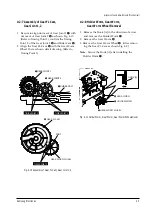
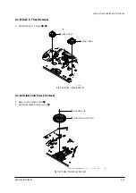
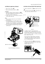
4-2-4 Lever FL Arm Ass’y Removal
1. Remove the Lever FL Door. (Refer to Fig. 4-5
2. Remove the Holder FL Cassette AssÕy.
(Refer to Fig.4-6)
3. Release the Hook
Œ
in the direction of arreow
ÒAÓ, pull out the Lever FL Arm AssÕy
¨
from
the Boss of Main Base.
4. Remove the Lever FL Arm AssÕy
¨
in the direc-
tion of arrow ÒBÓ.
Assembly
: When reinstalling, be sure to reassemble
Lever FL Arm AssÕy
¨
after you insert the Boss
´
in Groove [A] of Slider FL Drive
ˇ
.
Œ
HOOK
´
BOSS
¨
LEVER FL
ARM ASS'Y
ˇ
SLIDER FL DRIVE
GROOVE [A]
"A"
"B"
Fig. 4-6 Holder FL Cassette Ass’y Removal
Fig. 4-7 Lever FL Arm Ass’y Removal
Summary of Contents for TW14C52S/BWT
Page 89: ...11 Wiring Diagram 11 1 C15A Wiring Diagram Wiring Diagram Samsung Electronics 11 1 ...
Page 90: ...Wiring Diagram 11 2 Samsung Electronics 11 2 C15A Wiring Diagram ...
Page 94: ...Schematic Diagrams 12 4 Samsung Electronics 12 4 VCR POWER BLOCK ...
Page 97: ...Schematic Diagrams 12 7 Samsung Electronics 12 7 TV 3 4 RED POWER LINE BLUE SIGNAL LINE ...


