Alignments and Adjustments (Mechanical)
Samsung Electronics
4-21
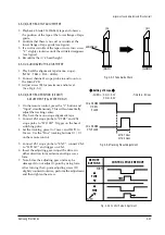
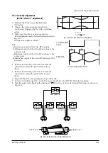
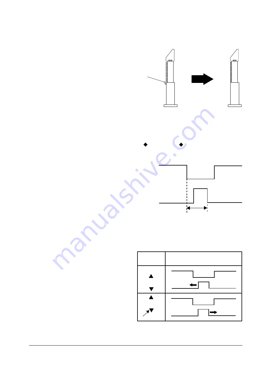
4-5-1(b) ACE HEAD TILT ADJUSTMENT
1. Playback a blank T160(E-240) tape and observe
the position of the tape at the lower flange of tape
guide.
2. Confirm that there is no curl or wrinkle at the
lower flange of tape guide (see figure).
3. If a curl or wrinkle of the tape occurrs, turn screw
ÒCÓ slighty clockwise until the wrinkle disappears
(see figure).
4. Reconfirm the A/C head height.
Fig. 4-5-3 Tape Guide Check
4-5-1(c) AUDIO AZIMUTH ADJUSTMENT
1. Play backthe alignment tape (mono scope).
(NTSC : 7KHz ; PAL : 6KHz).
2. Connect channel-1 scope probe to audio out on
the Main PCB.
3. Adjust screw (B) for maximum audio level.
(See Fig. 4-5-1)
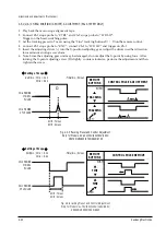
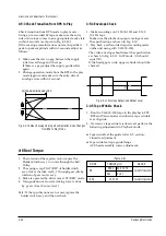
4-5-1(d) ACE HEAD POSITION (X-POINT)
ADJUSTMENT (PAL SYSTEM ONLY)
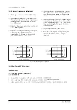
1. On the remote control, press the Ò1Ó button and
ÒInputÓ simultaneously. This will automatically
adjust the tracking center.
2. Play back the mono scope alignment tape.
3. Connect Ch1 scope probe to ÒCTRLÓ and Ch2
scope probe to ÒHÕD SWÓ. Trigger on the head-
switching pulse.
4. Set the tracking preset to 7 msec, and 2HÕD to
2 msec. Use the ÒFineÓ tracking buttons
▲
/
▼
on the remote control.
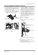
5. Connect Ch1 scope probe to ÒENVÓ; connect Ch-2
to ÒHÕD SWÓ and trigger on Ch-1.
6. Insert the adjusting gear. Adjust the driver in
either direction for maximum envelope wave
form.
7. Note: Since the adjusting gear unit may be
damaged, do not adjust X-point by using force.
After turning the X-point adjusting screw (D)
slightly counterclockwise, perform the adjustment
and then tighten the screw.
(A)
(B)
(BAD)
WRINKLE
(GOOD)
Fig. 4-5-4 Tracking Preset Adjustment
4H'd : 7msec
2H'd : 2mesc
CH-2 PROBE
H'D SW
PULSE
CH-1 PROBE
CTL PULSE
Setting of Scope
-Volt/div. ; CH-1 = 0.1V
CH-2 = 0.2V
-Time/div. ; 5msec
CONTROL PULSE REMOVE
REMOTE
BUTTONS
PUSH
FINE
FINE
PUSH
Fig. 4-5-5 Control Pulse Adjustment
Summary of Contents for TW14C52S/BWT
Page 89: ...11 Wiring Diagram 11 1 C15A Wiring Diagram Wiring Diagram Samsung Electronics 11 1 ...
Page 90: ...Wiring Diagram 11 2 Samsung Electronics 11 2 C15A Wiring Diagram ...
Page 94: ...Schematic Diagrams 12 4 Samsung Electronics 12 4 VCR POWER BLOCK ...
Page 97: ...Schematic Diagrams 12 7 Samsung Electronics 12 7 TV 3 4 RED POWER LINE BLUE SIGNAL LINE ...

