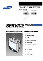


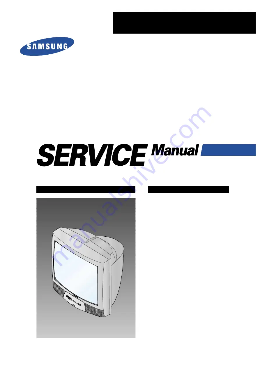
COLOR TELEVISION RECEIVER
Chassis :
KS2A(N)
Model :
TXK2750X/XAC
TXK2754X/XAC
TXK2754X/XAA
TXK2767X/XAA
TXK2767X/XAC
TXK2766X/XAA
TXK2768X/XAC
TXK2768X/XAA
COLOR TELEVISION RECEIVER
CONTENTS
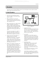
Precautions
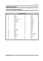
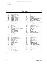
Reference Information
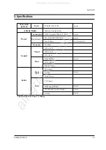
Specifications
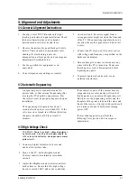
Alignment and Adjustments
Troubleshooting
Exploded Views and Parts List
Electrical Parts List
Block Diagrams
Wiring Diagram
Schematic Diagrams
1.
2.
3.
4.
5.
6.
7.
8.
9.
10.
All manuals and user guides at all-guides.com
all-guides.com


