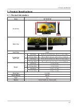
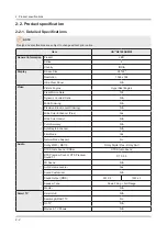
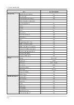
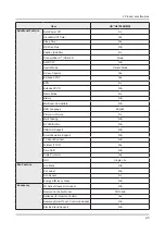
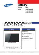
background image

3-2 

3. Disassembly and Reassemble

Description

Picture Description

Screws

4

 Remove the Rear-Cover.

5

Remove screws of Main Board and Power 

Board.

Torque :

7~ 8Kgf.cm

6001-003016

6

Remove a screw at Function Assy .

Torque :

7~ 8Kgf.cm

6001-003016

7

Remove the Speakers and Power Cables.

Summary of Contents for UA H4100AR Series

Page 1: ...LED TV SERVICE Manual LED TV Contents 1 Precautions 2 Product specifications 3 Disassembly and Reassembly 4 Troubleshooting 5 Wiring Diagram UA H4100AR Chassis U8BA Model UA28H4100AR UA32H4100AR ...

Page 2: ...tions 2 7 2 3 Accessories 2 8 3 Disassembly and Reassembly 3 1 3 1 Disassembly and Reassembly 3 1 3 2 Assy Board P Jog Switch Ir 3 4 3 3 Disassembly PTC 3 5 4 Troubleshooting 4 1 4 1 Troubleshooting 4 1 4 2 How to Check Fault Symptom 4 4 4 2 1 No Power and No Video 4 4 4 3 Factory Mode Adjustments 4 8 4 3 1 Detail Factory Option 4 8 4 3 2 Entering Factory Mode 4 9 4 4 White Balance 4 11 4 4 1 Adju...

Page 3: ...anual is a property of Samsung Electronics Co Ltd Any unauthorized use of Manual can be punished under applicable International and or domestic law 2014 Samsung Electronics Co Ltd All rights reserved Printed in Korea ...

Page 4: ...s adjustment and 2 compartment covers or shields isolation resistorcapacitor networks mechanical insulators etc Leakage Current Hot Check 3 DEVICE UNDER TEST READING SHOULD NOT BE ABOVE 0 5mA LEAKAGE CURRENT TESTER TEST ALL EXPOSED METAL SURFACES 2 WIRE CORD ALSO TEST WITH PLUG REVERSED USING AC ADAPTER PLUG AS REQUIRED EARTH GROUND WARNING Do not use an isolation transformer during this test Use ...

Page 5: ...ed by replacing them with components rated for higher voltage wattage etc Parts that have special safety characteristics are identified by on schematics and parts lists A substitute replacement that does not have the same safety characteristics as the recommended replacement part might create shock fire and or other hazards Product safety is under review continuously and new instructions are issue...

Page 6: ... used 2 The internal wiring is sometimes clamped to prevent contact with thermally hot components Reinstall all such elements to their original position After servicing always check that the screws components and wiring have been correctly reinstalled Make sure that 3 the area around the serviced part has not been damaged Check the insulation between the blades of the AC plug and accessible conduc...

Page 7: ...s sufficient to damage ESDs 3 Use only a grounded tip soldering iron to solder or desolder ESDs 4 Use only an anti static solder removal device Some solder removal devices not classified as anti static can generate 5 electrical charges sufficient to damage ESDs Do not remove a replacement ESD from its protective package until you are ready to install it Most replacement ESDs 6 are packaged with le...

Page 8: ...antenna far away from any high voltage cables and install it firmly Contact with the highvoltage cable or the 6 antenna falling over may cause fire or electric shock When installing the product leave enough space 0 4m between the product and the wall for ventilation purposes 7 A rise in temperature within the product may cause fire If an equipment is provided with a replaceable battery and if repl...

Page 9: ... 3 x 17 1 x 8 0 inches Without Stand 643 4 x 396 5 x 62 9 mm 25 3 x 15 6 x 2 5 inches 32 With Stand 736 1 x 485 5 x 203 2 mm 29 0 x 19 1 x 8 0 inches Without Stand 736 1 x 447 4 x 62 9 mm 29 0 x 17 6 x 2 5 inches Weight 28 With Stand 4 0 kg 8 9 lbs Without Stand 3 8 kg 8 4 lbs 32 With Stand 5 3 kg 11 7 lbs Without Stand 4 9 kg 10 8 lbs Panel Type Anti Glare Internal Memory 64Mbtye DDR None Feature...

Page 10: ...100 Dynamic Contrast Ratio N A Micro Dimming N A Precision Black Local Dimming N A Wide Color Enhancer Plus Yes Wide Color Gamut N A Color Accuracy N A Auto Depth Enhancer N A Film Mode Yes Natural Mode Support No Audio Dolby MS10 MS110 Dolby Digital Plus Dolby AAC DTS Studio Sound DNSe DTS Studio Sound DTS Premium Sound DTS Premium Sound 5 1 DTS 2 0 3D Sound N A Auto Volume Leveler Yes Sound Cust...

Page 11: ...Interaction N A Voice Control N A Camera Built in N A Face recognition N A Motion control N A Samsung Apps supported N A Smart Convergence Contents Streaming N A Screen Mirroring N A Samsung SMART View N A Smart Home N A Wake On LAN N A WiDi N A Tuner Broadcasting DTV Tuner Ready Analog Tuner Yes MHP MHEG HbbTV ACAP GINGA OHTV No Connectivity HDMI 2 USB 2 Component In Y Pb Pr 1 Composite In AV 1 C...

Page 12: ... LTE N A HDMI 1 4 3D Auto Setting N A HDMI 1 4 A Return Ch Support N A InstaPort S HDMI quick switch N A Wireless LAN Adapter Support N A Wireless LAN Built in N A Anynet HDMI CEC N A Design Design Wavy Line Bezel Type NNB Slim Type Slim 1 49mm Front Color Black Light Effect Deco N A Stand Type Round Swivel Left Right N A Camera Type N A Additional Feature Samsung 3D N A 3D Converter N A Instant O...

Page 13: ...ry N A Multiroom Compatible N A OSD Language English Picture In Picture No Multi Tasking N A BT HID Built in N A USB HID Support N A Smart Evolution Support N A TV SoundConnect N A Teletext TTXT Yes Time Shift N A Triple Protector Yes GUI Single Lite Eco Feature Eco Mark N A Eco Label N A Eco Sensor No Energy Efficiency Class N A Accessory 3D Active Glasses Included N A Remote Controller Model TM1...

Page 14: ...ted N A Mini Wall Mount Supported Yes Vesa Wall Mount Supported Yes Floor Stand Support N A TV Camera Included N A IR Extender Cable Included N A Network Speaker Included N A Wireless Keyboard Included N A Wireless LAN Adaptor Included N A User Manual Yes E Manual No ANT Cable N A Power Cable Yes Slim Gender Cable N A ...

Page 15: ... 16 7M color Display Resolution 1 366 x 768 Input Signal Analog 0 7 Vp p 5 positive at 75Ω internally terminated Input Sync Signal H V Separate TTL P or N Maximum Pixel Clock Rate 78MHz AC Power Voltage Frequency AC100 240V 50 60Hz Environmental Considerations Operating Temperature 50 F 104 F 10 C 40 C Operating Humidity 10 80 non condensing Storage Temperature 4 F 113 F 20 C 45 C Storage Humidity...

Page 16: ...tents can be purchased separately The part code for some accessories may differ depending on your region Product Code No Product Code No Remote Control BN59 01175M User Manual BN68 05733E Batteries AAA x 2 4301 000121 Warranty Card Not available in some locations 6801 001984 Power Cord 3903 000844 Image Product Code No Holder Wire Stand BN61 08370A ...

Page 17: ...ly and Reassembly CAUTION Disconnect the LED TV from the power source before disassembly 1 Follow these directions carefully never use metal instruments to pry apart the cabinet 2 If there is no additional coment it is same for all inches 3 Description Picture Description Screws 1 Place TV face down on cushioned table 2 Remove screws from the Stand and Remove Stand Torque 9 10Kgf cm 6003 001782 3 ...

Page 18: ...scription Picture Description Screws 4 Remove the Rear Cover 5 Remove screws of Main Board and Power Board Torque 7 8Kgf cm 6001 003016 6 Remove a screw at Function Assy Torque 7 8Kgf cm 6001 003016 7 Remove the Speakers and Power Cables ...

Page 19: ...assembly and Reassemble Description Picture Description Screws 8 Remove the LVDS Cable and Panel Drive Cable 9 Completed disassembly NOTE Reassembly procedures are in the reverse order of disassembly procedures ...

Page 20: ... Reassemble 3 2 Assy Board P Jog Switch Ir How to disassembly Description Picture Description Refer 1 open the Back cover 2 Pull out jog function NOTE Reassembly procedures are in the reverse order of disassembly procedures ...

Page 21: ...nd Reassemble 3 3 Disassembly PTC How to disassembly Description Picture Description Refer 1 Place TV face up on cushioned table 2 Products at the top of the central TOP CHASSIS is rotated by 45 degrees outward and pulls ...

Page 22: ... Description Refer 3 Pull in the same way from the center of the top 4 Pull the left part of the product as shown while holding the raised portion on figure 3 5 Pull the bottom part of the product as figure 2 while holding the raised portion on figure 4 ...

Page 23: ...3 7 3 Disassembly and Reassemble Description Picture Description Refer 6 As shown in the picture Lift the bottom of the TOP CHASSIS 7 Pull the products at the bottom of the right side of the chassis ...

Page 24: ... the chassis with one hand and holding the bottom of the product after you pull the right side of the product chassis 9 Disassembly is complete CAUTION To use JIG Does not lift the chassis by hand JIG using the lift NOTE Reassembly procedures are in the reverse order of disassembly procedures ...

Page 25: ... If no Backlights unplug AC Power Cord unplug 14 pin connector to SMPS plug in AC Power Cord Back light should come on Check Main Board operation for error Power IR Indicator goes off Picture or banner is displayed If nothing is displayed check the LVDS cable 10P Cable Speaker Power Ass y 8P Cable Main Ass y LVDS Cable Main Board Assy CN201 9 A13V_PW 10 UNDER_DRIVER 7 A13V_PW 8 PWM_DIMMING_OUT 5 A...

Page 26: ... Service Mode If you do not have Factory remote control Power OFF Info MENU Mute Power On If you have Factory remote control INFO Factory Choose SVC 3 Choose Test pattern 4 Select the each pattern and then check all pattern is ok or not 5 Option SubOptions Debug SVC W B Adjust ADC Adjust Advanced Tuner Self Test Shop Option Test Pattern Mstar Test Pattern Pattern Status is Change the Test Pattern ...

Page 27: ...Power Tree 4 3 4 Troubleshooting ...

Page 28: ... Main Board Diagnostics Power cord on Yes Check Stand By A13V 13V appear at BD207_NOFF BN210_ OFF 13V CN201 3 5 7 9 No Cause There did not supply the power from SMPS Measure Change 10p power cable and SMPS Yes Set On Yes Check A_POWER Check A1 26V appear at 1 26V L203 Check A3 3V appear at 3 3V IC201 1 Check A5V appear at 5V L202 No Cause There did not supply the power from SMPS Measure Change 10p...

Page 29: ...V TP PANEL_VCC No Cause There is proble at FET or Main IC IC1001 did not control the SW_PVCC Measure Change the Main Assy Yes Change the LVDS cable No Change the Panel Caution Make sure to disconnect the power before working on the IP board 4 5 4 Troubleshooting ...

Page 30: ...Location of Parts Main Board_Front E A C D B Detail A B A5V B5V 1 2 5 6 C B3 3V 5 B3 3V 5 A3 3V 1 4 6 4 Troubleshooting ...

Page 31: ...Detail D A13V 3 5 7 9 D SW_POWER 6 E Panel Vcc 4 7 4 Troubleshooting ...

Page 32: ...re Type UA H4100ARMXL Inches 28 32 PANEL Vendor No data exist SDC Code BN95 01324A Spec LK315T3HC1K SMPS BOARD Vendor HANSOE Code BN44 00696C Spec L32S0N_EHS MAIN BOARD Chassis Ass y BN91 11940F PBA Ass y BN94 07133F Byte Item 0 Factory Reset No data exist 1 Type 32H6AH1S 2 Model H4100 3 SVC Model 4100 4 Local Set EA_INDIA 5 Tuner Ready 6 Ch table NONE 4 8 4 Troubleshooting ...

Page 33: ...l Power OFF MENU Info Menu mute Power ON If you have Factory remote control INFO Factory If you don t have Factory remote control can t control some menus Option SubOptions Sound Debug SVC W B Adjust ADC Adjust Advanced Tuner Self Test Shop Option T MXL0MASC Build Date Dec 16 2013 HDCP SUCCESS OPTION USB Serial OFF 4 9 4 Troubleshooting ...

Page 34: ...h Table Off TSE SDMA SAVINA SEIN TSEC SEIL_N SEIL_C NONE 6 Local Set EA_CHINA EA_INDIA EA_SRI EA_NEPAL EA_BANGLA EA_EGYPT EA_LIBYA EA_M_ASIA EA_SAUDI EA_PAK EA_E_ ASIA EA_AFR EA_S_AFR EA_MAL EA_PHI EA_VEIT EA_THAI EA_INA EA_INDIA 7 Tuner Ready 8 MRT Option LVDS Format JEIDA VESA JEIDA HVFlip On Off On TTX On Off On China HD On Off Off NT Conversion On Off Off Num of AV 0 1 2 1 Num of COMP 0 1 2 1 ...

Page 35: ...Adjustment Into the Factory Mode 1 Select 2 ADC WB menu Select 3 White Balance menu ADC WB White Balance Low Light Sub Brightness R offset G offset B offset Hight Light Sub Contrast R gain G gain B gain 4 11 4 Troubleshooting ...

Page 36: ...djustment HDMI Calibration at 24 Chessboard Pattern Manual adjustment at 92 pattern 720p COMP Calibration at 24 Chessboard Pattern Manual adjustment at 92 pattern 720p CVBS Calibration at 24 Chessboard Pattern Manual adjustment at 92 pattern NTSC Note If finishing in HDMI mode adjustment coordinate is almost same in AV COMP mode White Balance Manual adjustment Type LED_LOW RGB Measurement Levels C...

Page 37: ...4 0 004 0 02 0 004 0 004 0 02 80 IRE 0x08 X 0 004 0 004 0 01 0 004 0 004 0 01 90 IRE 0x09 X 0 004 0 004 0 01 0 004 0 004 0 01 100 IRE 0x0A X NA NA NA NA NA NA Target Gamma 2 30 Black x y Contrast 0 231 0 208 300000 Target xy Option x y Auto 0 282 0 299 Color Tone Target Spec High x y x y COOL 0 274 0 286 0 004 0 004 NORMAL 0 293 0 307 WARM2 0 328 0 353 Low x y x y COOL NA NA NA NA NORMAL NA NA WAR...

Page 38: ...ion 4 6 1 How to Check the Software Version Use the Main Menu Click the MENU key in remote controller 1 Select Support menu 2 Locate the menu cursor Software Upgrade menu 3 Click the INFO key 4 Check the Main SW and Micom version Use the Factory Mode Option SubOptions Sound Debug SVC W B Adjust ADC Adjust Advanced Tuner Self Test Shop Option T MXL0MASC Build Date Dec 16 2013 HDCP SUCCESS OPTION US...

Page 39: ...will have a higher number than the older version When software is upgraded video and audio settings you have made will return to their default factory settings We recommend you write down your settings before beginning firmware update After update is completed restore your previous settings Main Software Upgrade SSave the firmware folder to the root directory of a USB drive 1 Connect the USB Click...

Page 40: ...5 1 5 Wiring Diagram 5 Wiring Diagram 5 1 Wiring Diagram Main Board Power Board T CON Speaker FUNCTION IR Speaker CN201 CN1302_HD CN302 CN702 CN1 ...

Page 41: ...LVDS 9 TCON_WP 24 GND 10 TP818 25 EVEN_TX0 _LVDS 11 NC 26 EVEN_TX0 _LVDS 12 GND 27 GND 13 EVEN_TX3 _LVDS 28 TCON_SCL 14 EVEN_TX3 _LVDS 29 TCON_SDA 15 GND 30 NC 2 CN201 to Powr board 1 GND 6 SW_POWER_TO_ SMPS 2 GND 7 D13V_PW 3 A13V_PW 8 PWM_DIMMING_ OUT 4 GND 9 A13V_PW 5 D13V_PW 10 UNDER_DRIVER 3 CN401 FUNCTION 1 IR 5 MSDA 2 GND 6 KEY1 3 A3 3V 7 KEY2 4 MSCL 8 GND 5 2 Connector Main Board 8 CN302 1 ...

Page 42: ...B 13 GND 6 IDENT_COMP1 14 COMP1_SR_IN 7 GND 15 TEST_SR 8 COMP1_PR 6 CN401 HDMI 1 HDMI1_RX2 11 GND 2 GND 12 HDMI1_RXCLK 3 HDMI1_RX2 13 HDMI_CEC 4 HDMI1_RX1 14 GND 5 GND 15 SCL 6 HDMI1_RX1 16 SDA 7 HDMI1_RX0 17 GND 8 GND 18 5V 9 HDMI1_RX0 19 HPD 10 HDMI1_RXCLK 7 CN705 USB1 1 USB_VCC 3 USB_DP 2 USB_DM 4 GND 8 CN302 Audio Out 1 GND 5 NC 2 SL_OUT 6 IDENT 3 SR_OUT 7 GND 4 NC ...

Page 43: ...s Connector Function CN201 IP CN Supply main power and dimming signal from IP Board to Main Board CN1301_FHD T CON CNF1 The LVDS signal transfered from Main Board to Panel CN1302_HD T CON CNF1 The LVDS signal transfered from Main Board to Panel ...

Reviews: