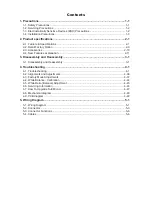
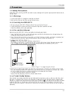
background image

1. Precautions

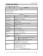
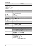
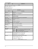
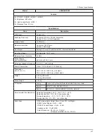
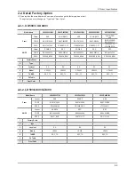
2. Product specification

s

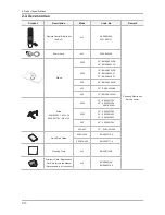
3. Disassembly and Reassembly

4. Troubleshooting

5. Wiring Diagram

LED/LCD-TV

LE32D400E1W

UE32D400*BW

Chassis : U57E 

Model  : UE40D500*BW
 

  UE26D400*BW 


  UE32D400*BW

Chassis : U57F 

Model  : UE22D500*BW
 

  UE19D400*BW

Chassis : U56G 

Model  : LE32D400E1W
 

  LE32D40*E2W


  LE40D50*F7W

SERVICE

Manual

TFT-LED/LCD TV

Contents

Summary of Contents for UE40D500 BW Series

Page 1: ...bly 4 Troubleshooting 5 Wiring Diagram LED LCD TV LE32D400E1W UE32D400 BW Chassis U57E Model UE40D500 BW UE26D400 BW UE32D400 BW Chassis U57F Model UE22D500 BW UE19D400 BW Chassis U56G Model LE32D400E1W LE32D40 E2W LE40D50 F7W SERVICE Manual TFT LED LCD TV Contents ...

Page 2: ...tures explanation 2 11 3 Disassembly and Reassembly 3 1 3 1 Disassembly and Reassembly 3 1 4 Troubleshooting 4 1 4 1 Troubleshooting 4 1 4 2 Alignments and Adjustments 4 36 4 3 Factory Mode Adjustments 4 37 4 4 White Balance Calibration 4 44 4 5 White Ratio Balance Adjustment 4 45 4 6 Servicing Information 4 46 4 7 How To Upgrade Sub Micom 4 47 4 8 Mechanical diagram 4 48 4 9 PCB diagram 4 49 5 Wi...

Page 3: ...anual is a property of Samsung Electronics Co Ltd Any unauthorized use of Manual can be punished under applicable International and or domestic law 2011 Samsung Electronics Co Ltd All rights reserved Printed in Korea ...

Page 4: ...th American National Standards Institute ANSI C101 1 Leakage Current for Appliances and Underwriters Laboratories UL Publication UL1410 59 7 With the unit completely reassembled plug the AC line cord directly into a 120V AC outlet With the unit s AC switch 4 first in the ON position and then OFF measure the current between a known earth ground metal water pipe conduit etc and all exposed metal par...

Page 5: ...trument s ground lead last 1 3 Electrostatically Sensitive Devices ESD Precautions Some semiconductor solid state devices can be easily damaged by static electricity Such components are commonly called Electrostatically Sensitive Devices ESD Examples of typical ESD are integrated circuits and some field effect transistors The following techniques will reduce the incidence of component damage cause...

Page 6: ...it from being exposed 4 to moisture Otherwise it may cause a fire or electric shock Make sure to turn the power off and unplug the power cord from the outlet before repositioning the product Also check 5 the antenna cable or the external connectors if they are fully unplugged Damage to the cord may cause fire or electric shock Keep the antenna far away from any high voltage cables and install it f...

Page 7: ...al 476 64 H x 268 11 V mm AC power voltage Frequency AC 110 V 220 V 60 Hz Power Consumption Under 110 W Under 0 3 W Stand by Dimensions Set W x D x H 515 8 x 124 x 350 0 mm_with stand 515 8 x 39 9 x 315 6 mm_without stand Weight 3 5 kg_with stand 3 4 kg_without stand Stand Weight 0 1 kg TV System Tuning Frequency Synthesize Refer to detailed Frequency Table System DVB T C PAL SECAM NT4 43 Sound BG...

Page 8: ...C power voltage Frequency AC 110 V 220 V 60 Hz Power Consumption Under 110 W Under 0 3 W Stand by Dimensions Set W x D x H 943 8 x 219 4 x 603 5 mm_with stand 943 8 x 51 0 x 561 4 mm_without stand Weight 11 kg_with stand 10 6 kg_without stand Stand Weight 0 4 kg TV System Tuning Frequency Synthesize Refer to detailed Frequency Table System DVB T C PAL SECAM NT4 43 Sound BG DK L L NICAM MPEG1 DD DD...

Page 9: ...C power voltage Frequency AC 110 V 220 V 60 Hz Power Consumption Under 110 W Under 0 3 W Stand by Dimensions Set W x D x H 447 2 x 124 x 312 4 mm_with stand 447 2 x 39 9 x 277 8 mm_without stand Weight 2 9 kg_with stand 2 8 kg_without stand Stand Weight 0 1 kg TV System Tuning Frequency Synthesize Refer to detailed Frequency Table System DVB T C PAL SECAM NT4 43 Sound BG DK L L NICAM MPEG1 DD DD H...

Page 10: ...AC power voltage Frequency AC 110 V 220 V 60 Hz Power Consumption Under 110 W Under 0 3 W Stand by Dimensions Set W x D x H 624 0 x 169 4 x 418 3 mm_with stand 624 0 x 45 1 x 377 2 mm_without stand Weight 4 4 kg_with stand 4 1 kg_without stand Stand Weight 0 3 kg TV System Tuning Frequency Synthesize Refer to detailed Frequency Table System DVB T C PAL SECAM NT4 43 Sound BG DK L L NICAM MPEG1 DD D...

Page 11: ...AC power voltage Frequency AC 110 V 220 V 60 Hz Power Consumption Under 110 W Under 0 3 W Stand by Dimensions Set W x D x H 756 4 x 182 4 x 498 1 mm_with stand 756 4 x 47 8 x 454 0 mm_without stand Weight 7 2 kg_with stand 6 3 kg_without stand Stand Weight 0 9 kg TV System Tuning Frequency Synthesize Refer to detailed Frequency Table System DVB T C PAL SECAM NT4 43 Sound BG DK L L NICAM MPEG1 DD D...

Page 12: ...power voltage Frequency AC 110 V 220 V 60 Hz Power Consumption Under 110 W Under 0 3 W Stand by Dimensions Set W x D x H 967 0 x 199 9 x 626 1 mm_with stand 967 0 x 107 1 x 586 3 mm_without stand Weight 13 25 kg_with stand 11 6 kg_without stand Stand Weight 1 65 kg TV System Tuning Frequency Synthesize Refer to detailed Frequency Table System DVB T C PAL SECAM NT4 43 Sound BG DK L L NICAM MPEG1 DD...

Page 13: ...ower voltage Frequency AC 110 V 220 V 60 Hz Power Consumption Under 110 W Under 0 3 W Stand by Dimensions Set W x D x H 784 4 x 181 9 x 542 3 mm_with stand 784 4 x 10³ 3 x 502 9 mm_without stand Weight 8 66 kg_with stand 7 65 kg_without stand Stand Weight 1 01 kg TV System Tuning Frequency Synthesize Refer to detailed Frequency Table System DVB T C PAL SECAM NT4 43 Sound BG DK L L NICAM MPEG1 DD D...

Page 14: ...power voltage Frequency AC 110 V 220 V 60 Hz Power Consumption Under 110 W Under 0 3 W Stand by Dimensions Set W x D x H 784 4 x 181 9 x 542 3 mm_with stand 784 4 x 10³ 3 x 502 9 mm_without stand Weight 9 2 kg_with stand 8 1 kg_without stand Stand Weight 1 1 kg TV System Tuning Frequency Synthesize Refer to detailed Frequency Table System DVB T C PAL SECAM NT4 43 Sound BG DK L L NICAM MPEG1 DD DD ...

Page 15: ...SEC POWER SEC SEC CODE BN44 00467A BN44 00473A BN44 00467A BN44 00471A BN44 00472A SPEC PD22A0_BPNV PD46G0_BSM PD22A0_BPNV PD26G0S_BSM PD32G0S_BSM 1 Factory Reset 2 Type 3 Local set EU EU EU EU EU 4 Model UD5003 UD5003 UD4003 UD4003 UD4003 5 TUNER SEC_TC SEC_TC SEC_TC SEC_TC SEC_TC 6 Ch Table 7 Front Color 2 2 2 LD503 LD403 LD400 Model Name LE40D503F7W LE32D403E2W LE32D400E1W Panel Vendor AML SHAR...

Page 16: ...BN90 03524C 32 BN90 03522C 503 40 BN90 03541B 403 32 BN90 03540B 400 32 BN90 03549A Screw 6001 002621 M4 x L8 6003 001782 M4 x L12 5003 22 6003 001782 40 6002 001294 6001 002621 4003 19 6003 001782 26 6002 001294 32 6001 002621 503 40 6002 001294 400 403 32 6002 001294 Quick Start Guide 5003 4003 BN68 03713A 503 403 400 BN68 03717A Cleaning Cloth ALL BN63 01798B Warranty Card Registration Card Saf...

Page 17: ...resolution of the image the longer it takes to display on the screen The maximum supported JPEG resolution is 15360X8640 pixels For unsupported or corrupted files the Not Supported File Format message is displayed If the files are sorted by Basic View up to 1000 files can be displayed in each folder MP3 files with DRM that have been downloaded from a non free site cannot be played Digital Rights M...

Page 18: ...ions are not displayed even if they are saved on the same USB device N If the sound is abnormal when playing MP3 files adjust the Equalizer in the Sound menu An over modulated MP3 file may cause a sound problem Playing selected music 02 Press the 1 C Edit Mode button Select the desired music 2 The check box appears to the left of the selected files Press the 3 TOOLS button and select Play Selected...

Page 19: ...o is displayed press the ENTERE button to start the slide show During the slide show all files in the file list will be displayed in order N When you press the Play button in the file list slide show will be started immediately N Music files can be automatically played during the Slide Show if the Background Music is set to On N The BGM Mode cannot be changed until the BGM has finished loading ...

Page 20: ...2 14 2 Product specifications 2 4 2 e Manual How to view the e Manual ...

Page 21: ...2 15 2 Product specifications ...

Page 22: ...andling these components 3 1 Disassembly and Reassembly Cautions 1 Disconnect the LED LCD TV from the power source before disassembly 2 Follow these directions carefully never use metal instruments to pry apart the cabinet LE32D400 Description Picture Description Screws 1 Place the TV face down on cushioned table Remove 4 screws from the Stand 6003 001785 Remove Stand 2 Remove the screws of Rear C...

Page 23: ... Screws 3 Lift up the Rear Cover 4 Remove the left and right speaker 5 Remove the 4 screws of Main Board Remove the 5 screws of SMPS Board 6003 001782 6 Remove the 6 screws of Bracket Stand Link Guide Machine type 4 EA 6003 001782 6003 001782 7 Remove the Stand Link ...

Page 24: ...3 3 3 Disassembly and Reassembly Description Picture Description Screws 8 Lift up the Panel Reassembly procedures are in the reverse order of disassembly procedures ...

Page 25: ...on cushioned table Remove 4 screws from the Stand machine type 6001 002621 Machine Remove Stand 2 Remove the screws of Rear Cover 26D4003 Remove the 4 screws 32D4003 Remove the 10 screws machine type 1 EA 40D5003 Remove the 11 screws machine type 3 EA 6003 001782 6001 002671 Machine 3 Lift up the Rear Cover ...

Page 26: ...t and right speaker 5 Remove the 4 screws of Main Board Remove the 5 screws of SMPS Board 6001 002653 Machine 6 Remove the 4 screws of Bracket Stand Link 6001 002653 Machine 7 Remove the Stand Link 8 Lift up the Panel Reassembly procedures are in the reverse order of disassembly procedures ...

Page 27: ...iption Screws 1 Place the TV face down on cushioned table Remove 2 screws from the stand machine type 6003 001782 Remove Stand 2 Remove the screws of Rear Cover 19D4003 22D5003 Remove the 4 screws 6003 001782 3 Lift up the Rear Cover 4 Remove the left and right speaker ...

Page 28: ...escription Picture Description Screws 5 Remove the 4 screws of Main Board Remove the 3 screws of SMPS Board 6003 000115 6 Remove the Stand Link 7 Lift up the Panel Reassembly procedures are in the reverse order of disassembly procedures ...

Page 29: ...re damaged or burnt Check to see if there is a disconnected or loose cable connection Check to see if the cables are connected according to the connection diagram Check the power input to the Main Board 2 UD4003 19 26 32 UD5003 22 40 MAIN BOARD SMPS BOARD T CON UD4003 19 UD5003 22 MAIN BOARD SMPS BOARD LD400 LD403 32 LD503 40 MAIN BOARD SMPS BOARD T CON ...

Page 30: ...output voltage of SMPS Replace the Main Board Diagnostics Yes Change the 14p power cable No Lamp Backlight Off power indicator LED on Yes Change INVERTER BALANCE B D No Lamp Backlight Off power indicator LED on Yes Change the LVDS cable No Does proper DC B13V appear at LVDS connector Pin 1 5 of T con b d Yes Change the T con b d No Does proper DC B13V appear at F1 of T con b d Check a other functi...

Page 31: ...4 3 4 Troubleshooting Main Board_Bottom ...

Page 32: ...DMI2 HDMI RX_Clk RX_Data Does the digital data appear at TP E_TXCLK E_TXCLK O_TXCLK O_TXCLK Yes Yes Yes Yes Check a set in the Stand by mode Input the HDMI signal properly Please Contact Tech support Check CN601 CN604 CN602 CN603 Check HDMI cable Change the Main Assy Check IC1001 X6 Change the Main Assy No No No No No Power indicator LED is off Lamp Backlight on no video Check the HDMI source and ...

Page 33: ...4 5 4 Troubleshooting Main Board_Top ...

Page 34: ...4 6 4 Troubleshooting WAVEFORMS 3 HDMI input RX_Data RX_Clk 2 LVDS output ...

Page 35: ...ar at TP TUNER_33V B 5V Pin of Tuner Does the digital data appear at TP E_TXCLK E_TXCLK O_TXCLK O_TXCLK Yes Yes Yes Yes Check a set in the Stand by mode Input the RF source properly Please Contact Tech support Change the Main Assy Check IC1001 X6 Change the Main Assy No No No No No Power indicator LED is off Lamp Backlight on no video Check the RF source and check the connection of RF cable Check ...

Page 36: ...4 8 4 Troubleshooting Main Board_Top ...

Page 37: ...4 9 4 Troubleshooting WAVEFORMS 2 LVDS output ...

Page 38: ...ength in Self Diagnosis menu Strength is enough Does the digital data appear at TP E_TXCLK E_TXCLK O_TXCLK O_TXCLK Yes Yes Yes Yes Yes Check a set in the Stand by mode Input the RF source properly Please Contact Tech support Change the Main Assy Check the D TV source Check IC1001 X6 Change the Main Assy No No No No No No Power indicator LED is off Lamp Backlight on no video Check the RF source and...

Page 39: ...4 11 4 Troubleshooting Main Board_Top ...

Page 40: ...4 12 4 Troubleshooting WAVEFORMS 2 LVDS output ...

Page 41: ..._CVBS Does the digital data appear at TP E_TXCLK E_TXCLK O_TXCLK O_TXCLK Yes Yes Yes Yes Check a set in the Stand by mode Input the video source properly Please Contact Tech support Check CN503 Change the Main Assy Check IC1001 X6 Change the Main Assy No No No No No Power indicator LED is off Lamp Backlight on no video Check the video source and check the connection of video cable Check the LVDS c...

Page 42: ...4 14 4 Troubleshooting Main Board_Top ...

Page 43: ...4 15 4 Troubleshooting WAVEFORMS 4 CVBS OUT Grey Bar 2 LVDS output ...

Page 44: ...he sound data appear at PIN COMP1_SR_IN COMP1_SL_IN VIA PC_DVI_SR_IN PC_DVI_SL_IN PC DVI Does the sound data appear at TP SPK_ L SPK_L SPK_R SPK_R Yes Yes Yes Yes Input the sound source properly Please Contact Tech support Change the Main Assy Check CN503 CN402 Change the Main Assy Check IC1001 X6 Change the Main Assy No No No No No Check the source and check the connection of sound cable Comp PC ...

Page 45: ...4 17 4 Troubleshooting Main Board_Bottom ...

Page 46: ...4 18 4 Troubleshooting WAVEFORMS 7 Speaker out ...

Page 47: ...f each part Check the output voltage of SMPS Replace the Main Board Diagnostics Yes Change the 14p power cable No Lamp Backlight Off power indicator LED on Yes Change INVERTER BALANCE B D No Lamp Backlight Off power indicator LED on Yes Change the LVDS cable No Does proper DC B13V appear at LVDS connector Pin 1 5 of Panel Check a other function No picture part Replace a LCD Panel No A power is sup...

Page 48: ...4 20 4 Troubleshooting Main Board_Bottom ...

Page 49: ... 12 7 HDMI2 HDMI RX_Clk RX_Data Does the digital data appear at TP E_TXCLK E_TXCLK O_TXCLK O_TXCLK Yes Yes Yes Yes Check a set in the Stand by mode Input the HDMI signal properly Please Contact Tech support Check CN601 CN602 Check HDMI cable Change the Main Assy Check IC1111 X5 Change the Main Assy No No No No No Power indicator LED is off Lamp Backlight on no video Check the HDMI source and check...

Page 50: ...4 22 4 Troubleshooting Main Board_Top ...

Page 51: ...4 23 4 Troubleshooting WAVEFORMS 3 HDMI input RX_Data RX_Clk 2 LVDS output ...

Page 52: ...TU_PW appear at 2 4 Pin of Tuner Does the digital data appear at TP E_TXCLK E_TXCLK O_TXCLK O_TXCLK Yes Yes Yes Yes Check a set in the Stand by mode Input the RF source properly Please Contact Tech support Change the Main Assy Check IC1111 X5 Change the Main Assy No No No No No Power indicator LED is off Lamp Backlight on no video Check the RF source and check the connection of RF cable Check the ...

Page 53: ...4 25 4 Troubleshooting Main Board_Top ...

Page 54: ...4 26 4 Troubleshooting WAVEFORMS 2 LVDS output ...

Page 55: ...e signal strength in Self Diagnosis menu Strength is enough Does the digital data appear at TP E_TXCLK E_TXCLK O_TXCLK O_TXCLK Yes Yes Yes Yes Yes Check a set in the Stand by mode Input the RF source properly Please Contact Tech support Change the Main Assy Check the D TV source Check IC1111 X5 Change the Main Assy No No No No No No Power indicator LED is off Lamp Backlight on no video Check the c...

Page 56: ...4 28 4 Troubleshooting Main Board_Top ...

Page 57: ...4 29 4 Troubleshooting WAVEFORMS 2 LVDS output ...

Page 58: ...VBS Does the digital data appear at TP E_TXCLK E_TXCLK O_TXCLK O_TXCLK Yes Yes Yes Yes Check a set in the Stand by mode Input the video source properly Please Contact Tech support Check CN502_NEU Change the Main Assy Check IC1111 X5 Change the Main Assy No No No No No Power indicator LED is off Lamp Backlight on no video Check the video source and check the connection of video cable Check the LVDS...

Page 59: ...4 31 4 Troubleshooting Main Board_Top ...

Page 60: ...4 32 4 Troubleshooting WAVEFORMS 4 CVBS OUT Grey Bar 2 LVDS output ...

Page 61: ...CN201 PIN 7 9 B12VS_PW Does the sound data appear at PIN COMP2_SR_IN COMP2_SL_IN Does the sound data appear at TP SPK_ L SPK_L SPK_R SPK_R Yes Yes Yes Yes Input the sound source properly Please Contact Tech support Change the Main Assy Check CN502_NEU Change the Main Assy Check IC1111 X5 Change the Main Assy No No No No No Check the source and check the connection of sound cable HDMI Replace speak...

Page 62: ...4 34 4 Troubleshooting Main Board_Bottom ...

Page 63: ...4 35 4 Troubleshooting WAVEFORMS 7 Speaker out ...

Page 64: ...hing is essential 3 Avoid overload Excessive signal from a sweep generator might overload the front end of the TV 4 When inserting signal markers do not allow the marker generator to distort test result Connect the TV only to an AC power source with voltage and frequency as specified on the backcover nameplate 5 Do not attempt to connect or disconnect any wire while the TV is turned on 6 Make sure...

Page 65: ... Option Control SVC Expert ADC WB Advanced T MSU D C XXXX T MSU D S XXXX E Manual XXXXXXXXXX XXXX EDID SUCCESS HDCP SUCCESS CALIB AV COMP PC HDMI Option XXXX XXXX T MSXDXX XXXX SDAL X XX X X RFS Mstar X5 XXXX 20XX XX XX F ET 0xXX XXXX Type XXXXXXXX Model XXXXXXXX CIP SUCCESS LOCK X Factory Data Ver XX EERC Version XXX DTP AP COMP XXX DTP BP HAL XXXX DTP BP XXXX XX Date Of Purchase XX XX XXXX OPTIO...

Page 66: ...D4000 UD4010 UD5000 UD5500 UD5550 UD5700 PD450 PD451 PD460 PD490 PD491 PD540 PD541 PD550 PD551 PD560 PD570 PD6400 PD6500 PD6600 PD6900 PD7000 LD460H LD463H LD467H LD468H LD560H LD568H LD580H UD4000H UD5000H UD5500H LD567H PD6452 PD6910 PD580 PD480 PD452 PD420 LD430 LD530 UD4020 UD5010 LD531 LD551 PD495 PD6905 PD6915 PD7005 UD5030 LD451 LD455 LD481 LD555 LD556 LD575 LD578 LD579 LD585 UD4005 UD4015 ...

Page 67: ...ID WRITE HDMI3 EDID WRITE HDMI4 EDID VER EDID PORT EDID WRITE DVI Sub Option RS 232 Jack UART Debug Logic UART Select Setting of UART port Initial value is UART Watchdog ON ON OFF Select Watchdog Initial value is ON WD Count 0 255 Watchdog Count Read Only Dimm Type EXT fixed Select Dimming Type Initial value is EXT Lvds Format JEIDA JEIDA VESA 19INCH Select LVDS format 19 22 27inch VESA other inch...

Page 68: ...und of stereo multiplex Speaker EQ ON ON OFF Control for sound precision SVC Factory Name Data Range Use Test Pattern Panel Auto Setting Panel Display Time 0Hr Logic Usb D L off Tuner Status T CON Usb Download MICOM UPGRADE off Set ON Sub micom upgrade after upgrade Main Micom over 5 minutes BT ADDRESS 0 BT UPGRADE SVC Reset Test Pattern Pattern Sel OFF OFF White Black Red Green Blue Cross OneDot ...

Page 69: ...dified ISDB T FFT Size_1 Not modified Guard Interval_1 Not modified Freq Offset_1 Not modified SNR_1 Not modified IF AGC_1 Not modified TMCC Lock_1 Not modified TS Packet_1 Not modified Master Lock_1 Not modified A_Modulation_1 Not modified A_Code Rate_1 Not modified A_Timer InterLeave_1 Not modified A_Segments Num_1 Not modified A_Ber_1 Not modified B_Modulation_ Not modified B_Code Rate_1 Not mo...

Page 70: ...1st_COMP_Cb_Low 512 0 1020 1st_COMP_Cr_Low 512 0 1020 1st_COMP_Y_High 940 0 1020 1st_COMP_Cb_High 512 0 1020 1st_COMP_Cr_High 512 0 1020 1st_COMP_Delta 2 0 7 1st_PC_Low 4 0 1020 1st_PC_High 1004 0 1020 1st_PC_Delta 2 0 7 2nd_ACH_Low 4 0 124 2nd_ACH_High 940 0 1020 2nd_PC_Low 4 0 124 2nd_PC_High 940 0 1020 2nd_Delta 2 0 7 ADC RESULT 1st_Y_GH 0 0 511 1st_Y_GL 0 0 255 1st_Cb_BH 0 0 511 1st_Cb_BL 0 0 ...

Page 71: ...128 0 255 R_Offset 128 0 255 G_Offset 128 0 255 B_Offset 128 0 255 Sub Contrast 128 0 255 R_Gain 128 0 255 G_Gain 128 0 255 B_Gain 128 0 255 Movie R Offset 512 0 1023 Movie B Offset 512 0 1023 Movie R Gain 512 0 1023 Movie B Gain 512 0 1023 ...

Page 72: ...alance Calibration 1 Calibration AV Calibration Comp Calibration PC Calibration HDMI Calibration 4 4 2 White Balance Adjustment 3 W B low light hight light Sub Bright R offset G offset B offset Sub Contrast R gain G gain B gain W B adjustment Condition refer next page ...

Page 73: ...ion and Manual setting for WB adjustment HDMI Calibration at 24 Chessboard Pattern Manual adjustment 92 pattern 720p COMP Calibration at 24 Chessboard Pattern Manual adjustment at 92 pattern 720p CVBS Calibration at 24 Chessboard Pattern Manual adjustment at 92 pattern PAL If finishing in HDMI mode adjustment coordinate is almost same in AV COMP mode White Balance Manual Adjustment P Mode Adjustme...

Page 74: ...ENTER button to select By USB The message Scanning for USB It may take up to 1 minute is displayed The message Upgrade version XXXX to version XXXX 4 The system will be reset after upgrade is displayed Press the or to select the OK then press the ENTER button Please be careful to not disconnect the power or remove the USB drive while upgrades are being applied The TV will turn off and turn on auto...

Page 75: ...mode If you don t have DDC Manager Use this method Into the Factory Mode 1 Select SVC Use 2 r button Select MICOM UPGRADE off use 3 r button If message change from off to wait TV is upgrading Sub S W It takes about 5 min 4 If update completes TV set will booting automatically 5 ...

Page 76: ... 39 9 x 315 6 943 8 x 51 0 x 561 4 447 2 x 39 9 x 277 8 624 0 x 45 1 x 377 2 756 4 x 47 8 x 454 0 Weight Kg Set with Stand 3 5 11 2 9 4 4 7 2 Set without Stand 3 4 9 6 2 8 4 1 6 3 4 8 2 LD503_403 40D503 32D403 32D400 Size mm Set with Stand W x D x H 967 0 x 199 9 x 626 1 784 4 x 181 9 x 542 3 784 4 x 182 4 x 545 3 Set without Stand W x D x H1 967 0 x 107 1 x 586 3 784 4 x 10³ 3 x 502 9 784 4 x 88 ...

Page 77: ...4 49 4 Troubleshooting 4 9 PCB diagram 4 9 1 PCB layout Flip UE40D5003BW UE26 32D4003BW LE40D503F7W LE32D400E1W LE32D403E2W PCB ...

Page 78: ...4 50 4 Troubleshooting TOP BOTTOM INNER 1 INNER 2 ...

Page 79: ...4 51 4 Troubleshooting Non Filp UE22D5003BW UE19D4003BW PCB ...

Page 80: ...4 52 4 Troubleshooting TOP BOTTOM INNER 1 INNER 2 ...

Page 81: ...4 53 4 Troubleshooting SMPS_UD4003 19 Model Inch CODE P N UD4003 19 BN44 00467A PD22A0_BPNV SMPS_UD4003 26 Model Inch CODE P N UD4003 26 BN44 00471A PSLF800A03G ...

Page 82: ...4 54 4 Troubleshooting SMPS_UD4003 32 Model Inch CODE P N UD4003 32 BN44 00472A PSLF800A03S SMPS_UD5003 22 Model Inch CODE P N UD5003 22 BN44 00467A PD22A0_BPNV ...

Page 83: ...4 55 4 Troubleshooting UD5003 40 Model Inch CODE P N UD5003 40 BN44 00473A PSLF121A03S ...

Page 84: ...4 56 4 Troubleshooting SMPS_LD400 32 Model Inch CODE P N LD400 32 BN44 00438A PSIV121411A SMPS_LD403 32 Model Inch CODE P N LD403 32 BN44 00468A PSIV121411C ...

Page 85: ...4 57 4 Troubleshooting SMPS_LD503 32 Model Inch CODE P N LD503 32 BN44 00469B IV40F1_BHS ...

Page 86: ...5 1 5 Wiring Diagram 5 Wiring Diagram 5 1 Wiring Diagram 26 32 40 Main Board SMPS TCON Function IR SPEAKER SPEAKER Panel Inverter CN1201 CN302 CN1601_FHD CN201 ...

Page 87: ...5 2 5 Wiring Diagram 19 22 Main Board SMPS TCON Function IR SPEAKER SPEAKER CN1201 CN302 CN1601_HD CN201 ...

Page 88: ... 47 Panel_VCC 22 EVEN 2 48 Panel_VCC 23 EVEN 2 49 Panel_VCC 24 EVEN 1 50 Panel_VCC 25 EVEN 1 51 Panel_VCC 26 EVEN 0 FUNCTION CN901 1 IR 5 MSDA 2 GND 6 FUNC_INTR 3 3 3V 7 LED_STB 4 MSCL 8 NC CN1601_HD 1 Panel_VCC 16 ODDCLK 2 Panel_VCC 17 ODDCLK 3 Panel_VCC 18 GND 4 Panel_VCC 19 ODD 2 5 Panel_VCC 20 ODD 2 6 GND 21 GND 7 GND 22 ODD 1 8 GND 23 ODD 1 9 TCON_WP 24 GND 10 FORMAT 25 ODD 0 11 NC 26 ODD 0 1...

Page 89: ...15 SC_R_COMP1_PR 5 GND 16 SC_FB 6 SC_COMP1_SL_IN 17 GND 7 SC_B_COMP1_PB 18 GND 8 IDENT_SC 19 SC_CVBS_OUT 9 GND 20 SC_CVBS_IN 10 NC 21 GND 11 SC_G_COMP1_Y TUNER option by sec code DVB_TC BN40 00221A 1 RF_AGC 9 IF AGC 2 5V 10 DIF 1 3 GND 11 DIF 2 4 33V 12 AFT 5 GND 13 SIF 6 SCL 14 NC 7 SDA 15 CVBS 8 IF TP ...

Page 90: ... 9 TCON_WP 24 GND 10 FORMAT 25 EVEN 0 11 NC 26 EVEN 0 12 GND 27 GND 13 EVEN 3 28 SDA_TCON 14 EVEN 3 29 SCL_TCON 15 GND 30 NC FUNCTION CN901 1 IR 5 MSDA 2 GND 6 FUNC_INTR 3 3 3V 7 LED_STB 4 MSCL 8 NC SPEAKER CN302 1 R 3 L 2 R 4 L HEADPHONE CN301 1 GND 4 GND 2 HP_R 5 NC 3 HP_L 6 GND 7 IDENT_HP HDMI CN601 CN602 1 RX2 11 GND 2 GND 12 RXCLK 3 RX2 13 HDMI_CEC 4 RX1 14 NC 5 GND 15 SCL 6 RX1 16 SDA 7 RX0 ...

Page 91: ...Use LEAD Main IP 14P LEAD IP Invertor 12P LEAD IP Dirver B D 6P Code LD400 LD403 32 BN39 01449A LD503 32 BN39 01449C UD4003 19 BN39 01455G 26 BN39 01455E 32 BN39 01455D UD5003 22 BN39 01455E 40 BN39 01455K LD400 32 BN39 01448A LD403 32 BN39 01448E LD503 32 BN39 01448C UD4003 19 BN39 01465D UD5003 22 BN39 01465C Photo Use LVDS Main TCON Code FHD LD503 32 BN96 17116R UD5003 22 BN96 18829M 40 BN96 17...

Reviews: