


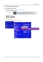


4-7. Factory Mode Adjustments
4-7-1. Entering Factory Mode
To enter [
1.
Service Mode
] press the remote-control keys in this sequence :
With Consumer Remote (IR Remote)
-
Remote Button :
9
NTSC
POWER OFF
MUTE
1
8
2
POWER ON
PAL
POWER OFF
INFO
MENU
MUTE
POWER ON
With Factory Remote
-
INFO
FACTORY
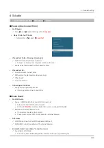
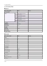
The following screen appears.
2.
Please refer to "
-
Detail Factory Option
page" for details.
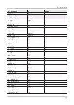
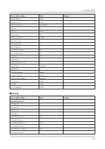
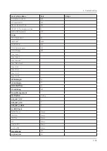
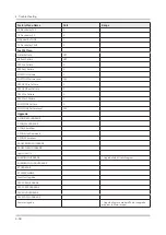
Detail Factory Option
4-23
4. Troubleshooting


