background image

Samsung Electronics

Classification

Class

Description

Installation

Q

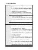
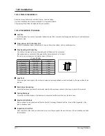
Who installs the air conditioner? (Relocation/Re-installation)   

A

  When  relocating  or  re-installing  the  air  conditioner,  make  sure  to  contact  Samsung  Electronics 
Service Center or Authorized Service Agent and have them to do the job. (If not, it could cause per-
sonal injury or product damage.) 
The cost for the relocation/re-installation of the air conditioner is subject to the customer's expense. 
There is a cost table. But, our service engineer needs to visit to total up the cost correctly. 
When you move in, make sure to contact Samsung Electronics Service Center or Authorized Service 
Agent in advance to streamline the process.    

Q

Is it possible to install the outdoor unit outside?  

A

 It is possible to install it at a designated place in the apartment or on the rooftop nearby.  


But, it's illegal hanging an angle iron case with the outdoor unit in it outside the apartment.
Also, it is illegal obstructing passers-by with the outdoor unit installed outside.   

Q

What can be done to install the outdoor unit facing the road because it is a commercial build-
ing? 


A

 The following is an excerpt from Building Code going into effect from JUNE 1st 2005. "The exhaust 
pipe of a cooling or ventilation facility installed in a building adjacent to the streets of commercial or 
residential areas shall be installed higher than 2 m to prevent the exhaust air from blowing directly to 
passers-by and the 
current facilities shall be corrected by MAY 31st 2005." So, please install it higher than 2 m or not to 
blow the hot exhausting air directly to passers-by.   

Q

What about installing a windscreen during installation not to blow hot air directly to passers-
by?  

A

 When the hot air from the front of the outdoor unit is blocked, the product's performance will be  
 affected and it will fail to operate properly. So, keep it at least 300mm away from its surrounding walls 
and give it good ventilation. 

14-5

 Q & A for Non-trouble

(cont.)

Summary of Contents for UH052EAMC

Page 1: ...ing Outdoor Unit High Ceiling Operation Up to 3 6m height Built in Drain Pump Max 750mm Long Piping SERVICE Manual CH105EAMC UH105GAMC CH070EAMC UH070EAMC CH052EAMC CH094EAMC UH052EAMC UH094EAM1C Basic CH44CA CH44CAX INDOOR UNIT OUTDOOR UNIT Model CH140EAMC UH140GAMC Model Code CH140EAMC UH140GAMC CH105EAMC UH105GAMC CH070EAMC UH070EAMC CH052EAMC UH052EAMC CH094EAMC UH094EAM1C ...

Page 2: ...e Specifications of Product 2 3 2 5 Accessory and Option Specifications 2 4 3 Alignment and Adjustments 3 1 3 1 Indoor Display Error and Check Method 3 1 3 2 Setting Option Setup Method 3 4 14 Disassembly and Reassembly 4 1 4 1 Indoor Unit 4 1 4 2 Outdoor Unit 4 10 15 Exploded Views and Parts List 5 1 5 1 Indoor Unit 5 1 5 2 Panel 5 4 5 3 Outdoor Unit 5 6 5 4 Ass y Control In 5 14 5 5 Ass y Contro...

Page 3: ...9 11 4 Wired Remote Controller Buttons and Display 11 10 12 Troubleshooting 12 1 12 1 Operation Specification 12 1 12 2 Troubleshooting 12 3 12 3 Sequence for trouble diagnosis 12 6 13 Block Diagram 13 13 1 Indoor Unit 13 13 2 Outdoor Unit 13 14 Reference Sheet 14 1 14 1 Index for Model Name 14 1 14 2 Pressure Graph 14 2 14 3 Pressure Capacity mark 14 2 14 4 Q A for Non trouble 14 3 14 5 Cleaning ...

Page 4: ...y an incorrect installation When installing the built in type air conditioner keep all electric cables such as the power cable and the connection cord in pipes ducts or cable channels to protect them from the danger of impact or any other incidents 1 2 Power supply and circuit breaker If the power cord of the air conditioner is damaged it must be replaced by the manufacturer or a qualified person ...

Page 5: ...ISO standard for energy efficiency 1 3 During operation Do not repair the air conditioner at your discretion It is recommended to contact a service center directly Never spill any kind of liquid on the air conditioner If this happens turn off the air conditioner and contact an authorized service center Do not insert anything between the airflow blades to prevent damage of the inner fan and consequ...

Page 6: ...technology words the definition of technology terms Abbreviated technology words Definition of technology terms COMP Full name compressor One that compresses especially a machine used to compress gases BLOWER One that blows especially a mechanical device such as a fan that pro duces a current of air FAN A device for creating a current of air or a breeze ASSY CONTROL BOX Full name assemble control ...

Page 7: ...N62YFAMT AN42YBFMT G5A240JUAEM Output Btu h 56 640 37 200 24 100 Protection External External Internal Refrigerant Type R410A R410A R410A Charge g 3 300 116 4oz 2 750 97 0oz 1 700 60oz Adding Charge g m 70 70 40 Control Expansion Valve Expansion Valve Expansion Valve Heat Exchanger Type Slit Φ7 Wide fin Slit Φ7 norm al fin Slit Φ7 norm al fin RowsxStagesxFin pitch 2 52 1 4 2 42 1 3 2 28 1 4 Dimens...

Page 8: ... Unit Outdoor Unit Net Weight Indoor Unit 29Kg 34Kg Outdoor Unit 121Kg 123Kg Outer Dimension WxHxD Indoor Unit 298 840 840mm 288 840 840mm Outdoor Unit 1128 932 375mm 1240 930 385mm Noise Indoor Unit 49dB 52dB Outdoor Unit 67dB 62dB Air Purifying System Filter Anti bacterial Filter Anti bacterial Filter 2 3 ...

Page 9: ...in in out DB62 03440H DB62 03439H 1 Insu Pipe Joint In 1 4 and 1 2 DB72 00143E DB72 00143G 1 Insu Pipe Joint Out 1 4 DB62 03439J 2 Cable tie DB65 10088C 8 Drain hose DB94 01065A 1 Pad Stopper DB69 00165A 1 Instruction manual DB98 26331A 1 Installation manual DB98 26330A 1 Safety net DB63 01480A 1 M4x12 tapped Screw 6002 2000213 4 2 4 2 5 1 Accessories ...

Page 10: ...Installation manual DB98 26328A 1 Accessories cont 2 5 2 Accessories Item Descriptions Code No Q TY Remark Wireless remote controller DB93 00251G 1 Battery DB47 90024A 2 Remote control holder DB61 00204A 1 STS 2S 2x10 tapped screw 6002 000581 2 Owner s instructions DB98 05156A 1 Installation manual DB98 05184A 1 Wireless Remote Controller Accessories Product Specifications 2 5 ...

Page 11: ...2 tapped screw 2 Owner s instructions DB98 05160A 1 Installation manual DB98 05186A 1 Wire kit DB39 00223A 1 Receiver display unit DB93 01066A 5 Standard type M4x16 tapped screw 7 Cable tie 2 Owner s instructions DB98 05160A 1 Installation manual DB98 05186A 1 Wire kit DB39 00223A 1 Receiver display unit Wire kit Product Specifications 2 6 ...

Page 12: ...le tie DB65 10088B 2 Cable clamp DB65 10074E 5 M4x16 tapped screw 6002 000474 7 Indoor unit power drawing cable DB39 00221A 1 Communication cable of the wired remote controller DB39 00933A 1 Wire joint DB39 90020A 1 Owner s instructions DB98 15731A 1 Installation manual DB98 15770A 1 Wired Remote Controller Accessories 2 7 ...

Page 13: ... clamp DB65 10074E 5 M4x16 tapped screw 6002 000474 7 Owner s instructions DB98 12721A 1 Owner s instructions DB98 12722A 1 Function Controller Accessories Item Descriptions Code No Q TY Remark Function controller DB93 00757G 1 Cable tie DB65 10088B 2 Cable clamp DB65 10074E 6 M4x16 tapped screw 6002 000474 7 Owner s instructions DB98 05164A 1 Owner s instructions DB98 05190A 1 2 8 ...

Page 14: ...Code No Q TY Remark Transmitter 1 Transmitter power cable 1 Transmitter communication cable 1 Installation manual 1 7 day Scheduler Accessories Item Descriptions Code No Q TY Remark 7 day Scheduler 1 Cable tie 2 Cable clamp 2 M4x16 tapped screw 4 Owner s instructions 1 Installation manual 1 ...

Page 15: ...re sensor in the indoor unit Open Short X X X X Error of heat exchanger sensor in the indoor unit X X Error of the outdoor temperature sensor Error of the condensor temperature sensor Error of the discharge temperature sensor X X X 1 Error of electronic expansion valve close 2 Error of electronic expansion valve open 3 2 nd detection of high temperature cond 4 2 nd detection of high temperature di...

Page 16: ...nge 1 No communication for 2 minutes between indoor units Communication error for more than 2 minutes 2 Indoor unit receiving the communication error from outdoor unit 3 Outdoor unit tracking 3 minutes error 4 When sending the communciation error from the outdoor unit the mismatching of the communication numbers and installed numbers after completion of tracking Communication error for more than 2...

Page 17: ...frost Error of the outdoor temperature sensor Open Short Error of condenser temperature sensor Open Short Error of discharge temperature sensor Open Short System down caused by communication error after completion of tracking Mismatching of the indoor unit numbers set with those communication after completion of 5 times tracking Error of temperature sensor in the indoor unit Open Short Error of th...

Page 18: ...s repeatedly Push the button to set the display panel to Every time you push the button the display panel reads repeatedly Push the button to set the display panel to Every time you push the button the display panel reads repeatedly 3 2 Setting Option Setup Method ex Option No Step 1 Enter the Option Setup mode 1st Take out the batteries of remote control 2nd Press the temperature button simultane...

Page 19: ...lay part to and check the display part The display part shows Press the Mode Selection key to set the display part to and check the display part The display part shows Step 4 Pressing the ON OFF button When pressing the operation ON OFF key with the direction of remote control for unit the sound Ding or Diriring is heard and the OPERATION ICON lamp of the display is flickering at the same time the...

Page 20: ... Grille 1 Open the Front Grille at about 45 degrees and draw it forward 2 Disassemble the Safety Clip 3 Filter Disassembly 1 Draw the Dust Collecting Filter forward 2 Disassemble the Filter 4 Disassembly and Reassembly 4 1 Indoor Unit Stop operation of the air conditioner and remove the power cord before repairing the unit 4 1 CH140 105 070 052 094EAMC ...

Page 21: ... Procedure Remark 4 Open the corner cover slowly to disas semble it There are three hooks 5 Pull the corner cover forward carefully by using two hands 6 Loosen four bolts of the front panel slowly 7 Loosen four screws of the safety net to disassemble it 4 2 ...

Page 22: ... screws in the mark 2 Draw the both side hooks toward the arrow direction 9 Disassemble two cables between the indoor unit and panel Stepping motor connector Receiving display unit connector wire 10 Hold on two hooks on both sides of the indoor unit and disassemble the Front Panel 11 Take away the disassembled Panel out of the main body ...

Page 23: ...l Indoor and Outdoor Cables connected to the Terminal Board 3 Fan Motor 1 Disassemble the Fan Motor Wire Connector Thermistor Wire Connector Drain Pump Wire Connector and Float Switch Wire Connector 2 Loosen four screws in the mark 3 Disassemble the Base Control from the main body Disassembly and Reassembly 4 4 ...

Page 24: ...the water in In this point you can check the Drain Pump Impeller operates well or not 5 Loosen eight bolts in the mark At first there are 2 bolts per one corner and when reassembly there should be at least 1 bolt per one corner fastened 2 Bolts per one corner recommended 6 Disassemble the Drain Cushion from the main body 7 Loosen the nut Disassembly and Reassembly 4 5 ...

Page 25: ...ts Procedure Remark 8 Take out the Washer 9 Lift the Fan to disassemble from the Motor 10 Loosen the screw and disassemble the Motor Connector to disassemble Motor 11 Loosen four screws in the mark Disassembly and Reassembly 4 6 ...

Page 26: ...assemble the Hose from the Drain Pump 2 Loosen the 3 bolts to disassemble the Drain Pump from the main body 5 Heat Exchanger 1 Loosen 2 screws to disassemble the Cover Pipe beside the main body 2 Loosen two screws fixing the Holder Evap to disassemble the Heat Exchanger Disassembly and Reassembly 4 6 4 7 ...

Page 27: ...o Parts Procedure Remark 6 Front Panel PCB Part 1 Loosen two screws to disassemble the Cover PCB 2 Loosen the screw fixing the PCB to dis assemble it 3 Disassemble the PCB Wire from the PCB 4 Disassemble the Button PCB from the PCB Disassembly and Reassembly 4 8 ...

Page 28: ...wo screws fixing the Cover Side There are 4 Cover Side 2 Draw two hooks then lift up the Cover Side 3 Disassemble the Stepping Motor Wire Connected 4 Disassemble the Stepping Motor from the Panel Front 5 Disassemble the link and bracket from the Stepping Motor Disassembly and Reassembly 4 9 ...

Page 29: ...the Control Box Cover 4 Pull out the assemble Cable 5 Disassemble the Cabinet Side 6 Disassemble the Cabinet Front Check whether each part is fixed to the electronic connector firmly at the time of part assembly 2 Fan Motor Propeller Fan 1 Loosen the blot fixing the Propeller Fan 2 Disassemble the Fan 4 2 Outdoor Unit Disassembly and Reassembly UH140GAMC ...

Page 30: ...ll out the assemble Cable 5 Disassemble the Cabinet Side 6 Disassemble the Cabinet Front Check whether each part is fixed to the electronic connector firmly at the time of part assembly 2 Fan Motor Propeller Fan 1 Loosen the blot fixing the Propeller Fan 2 Disassemble the Fan UH105GAMC UH070 052EAMC UH094EAM1C Note The above pictures are only references Disassembly and Reassembly ...

Page 31: ...Samsung Electronics 5 Exploded Views and Parts List 5 1 Indoor Unit 1 2 4 3 5 8 7 5 1 5 2 5 3 5 4 5 5 5 7 5 6 16 11 10 9 6 15 12 14 19 20 22 21 13 24 23 25 26 17 18 18 1 18 2 18 3 18 4 18 5 5 1 ...

Page 32: ...M 1 1 SNA 8 DB67 00682A FAN TURBO ABS GF20 1 1 SA 9 DB64 01562A CABI SIDE SGCC M 2 2 SA 10 DB90 02692A ASSY COVER PIPE ASSY 1 1 SA 11 DB90 02690A ASSY CABI FRONT ASSY SGCC M 1 1 SA 12 DB90 01950B ASSY COVER DRAIN PUMP ASSY 1 1 SA 13 DB94 01078A ASSY HOSE DRAIN ASSY 1 1 SA 14 DB61 02701A HOLDER EVAP STS301 2 2 SA 15 DB96 06221A ASSY EVAP UNIT ASSY 1 SA DB96 06405A ASSY EVAP UNIT ASSY 1 SA 16 DB90 0...

Page 33: ...C M 2 2 SA 10 DB90 02692A ASSY COVER PIPE ASSY 1 1 SA 11 DB90 03189A ASSY CABI FRONT ASSY SGCC M 1 1 SA 12 DB90 01950B ASSY COVER DRAIN PUMP ASSY 1 1 SA 13 DB90 01389A ASSY HOSE DRAIN ASSY 1 1 SA 14 DB61 03093A HOLDER EVAP STS430 2 2 SA 15 DB96 07779A ASSY EVAP UNIT ASSY 1 SA 1 SA 16 DB90 03190A ASSY CABI BACK ASSY SGCC M 1 1 SA 17 DB97 02090B ASSY PACKING SCREW M5X30 3 3 SNA 18 DB94 01381A ASSY D...

Page 34: ...Samsung Electronics 5 2 Panel 5 4 ...

Page 35: ... 11 DB63 01500A Cover PCB HIPS 1 SNA 12 DB66 01103A Link Motor A POM 1 SNA 13 DB66 01104A Link Motor B POM 1 SNA 14 DB61 02711A Holder Link Blade ABS BLK 8 SNA 15 DB66 01105A Link Blade POM 7 SNA 16 DB66 01106A Link Universal Joint POM 2 SNA 17 DB66 01107A Joint Universal POM 5 SNA 18 DB63 01486A Cover Side A HIPS BLK 1 SNA 19 DB63 01487A Cover Side B HIPS BLK 1 SNA 20 DB63 01488A Cover Side C HIP...

Page 36: ...Samsung Electronics 5 3 Outdoor Unit 16 14 9 11 25 18 13 15 19 4 24 17 23 20 2 3 5 6 22 21 12 1 7 8 20 6 20 5 20 1 20 4 20 3 20 2 10 UH140GAMC 5 6 ...

Page 37: ... SSEC 1 SNA 15 DB99 00795A ASS Y VALVE EXPANSION UH140GAMC SSEC 1 SNA 16 DB62 04288A INSU SOUND COMP UH140GAMC PVC FELT T11 5 SSEC 1 SNA 17 DB95 00564E ASS Y HEATER COMP UH140GZMC CHINA 1 SA 18 DB32 00102B THERMISTOR OUT 204CT 200K 25 3435K 20 150 50mA 5V 1 SA 19 DB32 00101B THERMISTOR OUT 204CT 200K 25 3435K 20 150 50mA 5V 1 SA 20 DB93 04138A ASS Y CONTROL OUT UH140GAMC SSEC 1 SA 20 1 DB61 01860A...

Page 38: ...Operating Instructions and Installation Samsung Electronics 9 8 7 6 1 22 23 15 11 3 10 5 4 12 13 14 16 20 21 2 18 17 19 24 UH105GAMC Exploded Views and Parts List 5 8 ...

Page 39: ...SEC 1 SA 11 DB90 01528A ASSY CABI FRONT RH ASS Y UH105GZMC 1 SNA 12 DB90 01526A ASSY PARTITION ASS Y UH105GZMC 1 SA 13 DB97 02613A ASSY BRACKET VAVLE ASSY SGCC M T1 6 SSEC 1 SA 14 DB61 01910A BRACKET WIRE UH140GZMC SSEC 1 SA 15 DB93 04375A ASSY CONTROL OUT HP 36K BTU AC 380V 1 SA 16 DB64 01231A HANDLE SC 90073R SSEC 3 SA 17 DB99 00836A ASSY VALVE EXPANSION UH105GAMC SSEC 1 SA 18 DB99 00835A ASSY V...

Page 40: ...Samsung Electronics UH052 070EAMC 17 16 19 8 14 15 18 1 6 20 21 3 2 12 11 13 10 5 7 10 2 10 10 1 10 3 10 8 10 7 10 6 10 4 5 9 4 16 1 Exploded Views and Parts List 5 10 ...

Page 41: ...10 6 2301 001379 C FILM LEAD OTHER 4000nF 10 5 450V BK 1 SNA 2301 001378 C FILM LEAD OTHER 4000nF 10 5 450V B 1 SNA 10 7 2501 001240 C OIL 50uF 450V BK 53x125mm 1 SNA 2501 001238 C OIL 50uF 450V BK 53x125mm 1 SNA 11 DB32 00102A THERMISTOR OUT 204CT 200K 25 3435K 1 1 SNA 12 DB32 00101A THERMISTOR OUT 204CT 200K 25 3435K 1 1 SNA 13 DB93 02919Y ASSY PCB MAIN UH052EAMC H P SSEC 1 SA DB93 02919T ASSY P...

Page 42: ...16 2 2 2 1 2 4 18 20 26 2 8 14 15 6 25 24 22 23 3 21 12 11 13 10 5 7 17 10 2 10 10 1 10 3 10 8 10 7 10 6 10 4 18 1 5 9 4 17 1 2 3 UH094EAM1C Exploded Views and Parts List 19 1 5 12 Samsung Electronics ...

Page 43: ...1 001367 C FILM LEAD OTHER 6000nF 10 5 450V BK 58x25x40mm 1 SA 10 7 2501 001236 C OIL 30uF 450V BK 53x85mm 20 6 2 SA 10 8 DB61 02319A CLIP CAPACITOR UH094EAMC SSEC 1 SA 11 DB32 00102A THERMISTOR OUT 204CT 200K 25 3435K 20 150 50mA 5V SSEC 1 SA 12 DB32 00101A THERMISTOR OUT 204CT 200K 25 3435K 20 150 50mA 5V SSEC 1 SA 13 DB93 02919C ASS Y PCB MAIN UH094EAMC SSEC 1 SA 14 DB90 40176B ASS Y COVER CONT...

Page 44: ...Samsung Electronics 5 4 Ass y Control In CH140EAMC DB93 04137A 5 14 ...

Page 45: ...8A 7 SNA 9 6009 001001 SCREW SPECIAL TH M4 L8 ZPC WHT SWRCH18A 3 SNA 10 DB68 02809A LABEL BAR CODE W170 L115 FOR PACKING CASE 1 SNA 11 DB39 01249A CONNECT WIRE UL1007 AWG 18 3P 280 BRN 1 SNA 12 DB39 01250A CONNECT WIRE UL1007 AWG 18 3P 350 BLK YH396 03V GP140078 1 SNA 13 DB39 01251A CONNECT WIRE UL1007 AWG 22 2P 370 RED YH396 02V GP140078 1 SNA 14 DB39 01251B CONNECT WIRE UL1007 AWG 22 2P 350 BLU ...

Page 46: ...Samsung Electronics CH105EAMC DB93 04376A Exploded Views and Parts List 5 16 ...

Page 47: ...EW SPECIAL TH M4 L8 ZPC WHT SWRCH18A 3 SNA 10 DB68 02809A LABEL BAR CODE W170 L115 FOR PACKING CASE 1 SNA 11 DB39 01249A CONNECT WIRE UL1007 AWG 18 3P 280 BRN 1 SNA 12 DB39 01250A CONNECT WIRE UL1007 AWG 18 3P 350 BLK YH396 03V GP140078 1 SNA 13 DB39 01251D CONNECT WIRE CH105EAMC AWG 22 UL1007 2 470 RED BLU 22 1 SNA 14 DB39 01251B CONNECT WIRE UL1007 AWG 22 2P 350 BLU YH396 02V GP140078 1 SNA 15 D...

Page 48: ...Samsung Electronics CH052 070 094EAMC DB93 05254A Exploded Views and Parts List 5 18 ...

Page 49: ...SNA 9 6009 001001 SCREW SPECIAL TH M4 L8 ZPC WHT SWRCH18A 3 SNA 10 DB68 02809A LABEL BAR CODE W170 L115 FOR PACKING CASE 1 SNA 11 DB39 01249A CONNECT WIRE UL1007 AWG 18 3P 280 BRN 1 SNA 12 DB39 01250A CONNECT WIRE UL1007 AWG 18 3P 350 BLK YH396 03V GP140078 1 SNA 13 DB39 01251D CONNECT WIRE CH105EAMC AWG 22 UL1007 2 470 RED BLU 22 1 SNA 14 DB39 01251B CONNECT WIRE UL1007 AWG 22 2P 350 BLU YH396 02...

Page 50: ...Samsung Electronics 5 5Ass y Control Out UH140GAMC DB93 04138A Exploded Views and Parts List 5 20 ...

Page 51: ... DB39 00987A CONNECT WIRE COMM UH140GCM UL1007 AW22 3P 1 SNA 17 DB39 01005A CONNECT WIRE COMP SIGNAL UH105 140 GZM 1 SA 18 DB39 01008B CONNECT WIRE COMP UH140GZM UL 1 SA 19 DB39 01006A CONNECT WIRE MAIN UH105GZM UL1015 1 SA 20 DB39 00189B CONNECT WIRE PHASE RFPC050H2M0 1 SA 21 DB39 00986A CONNECT WIRE POWER UH140GCM UL1015 AW18 1 SA 22 DB61 00206B HOLDER WIRE GALVA SBHG BLK SHRINK TUBE S PJT SSEC ...

Page 52: ...Operating Instructions and Installation Samsung Electronics UH105GAMC DB93 04375A Exploded Views and Parts List 5 22 ...

Page 53: ... UH105GZM UL1015 AWG 18 1 SNA 16 DB39 00987A CONNECT WIRE COMM UH140GCM UL1007 AW22 3P 1 SNA 17 DB39 01005A CONNECT WIRE COMP SIGNAL UH105 140 GZM 1 SA 18 DB39 01008B CONNECT WIRE COMP UH140GZM UL 1 SA 19 DB39 01006A CONNECT WIRE MAIN UH105GZM UL1015 1 SA 20 DB39 00189B CONNECT WIRE PHASE RFPC050H2M0 1 SA 21 DB39 00986A CONNECT WIRE POWER UH140GCM UL1015 AW18 1 SA 22 DB61 00206B HOLDER WIRE GALVA ...

Page 54: ...Samsung Electronics UH052 070EAMC DB93 04731B DB98 04731A Exploded Views and Parts List 5 24 ...

Page 55: ...TOR WIRE COMP AWG14 1 1 SNA 12 DB39 01251A CONNECT WIRE AWG22 L460 1 1 SNA 13 DB39 00938A CONNECT WIRE POWER AWG18 L300 1 1 SNA 14 DB93 02538A ASSY CONNECTOR WIRE POWER AWG14 L250 1 1 SNA 15 DB39 01005A CONNECT WIRE ASSY AWG18 L280 1 1 SNA 16 2501 001240 C OIL 50uF 450VAC 1 SNA 2501 001238 C OIL 40uF 450VAC 1 17 DB69 60008A BAND CAPACITOR SGCC M T0 8 1 1 SNA 18 DB68 02809A E PASS 1 1 SNA 19 DB73 2...

Page 56: ...R CHIP 2203 000444 1nF 10 50V X7R 2012 C901 1 SNA DIODE SWITCHING 0401 000133 LL4148 100V 200MA SOD 80C TP D900 927 28 SNA FUSE 3601 001308 250V 1 6A TIME LAG PLASTIC 8 4x7 6mm F702 1 SNA IC TR ARRAY 0506 000175 ULN2003D013TR IC05 09 5 SNA INDUCTOR RADIAL 2702 001123 4 7uH 10 6 5X7 5MM L101 1 SNA LED 0601 001373 ROUND RED 3MM 630NM LED11 1 SNA LED 0601 001375 ROUND GRN 3mm 570nm 3 8x5 3mm LED12 1 ...

Page 57: ... 112D3M 12VDC 3A RY70 RY71 2 SNA TRANS SWITCHING DB26 00046A EI2218 TINY PJT 110 240V FREE ST11 1 SNA SWITCH DIP 3407 000121 DS 04 24V 300mA SLIDE STAN DARD SW05 07 3 SNA RESONATOR CERAMIC 2802 001179 4MHZ 0 5 BK 8X3X5 5MM X301 1 SNA DIODE ZENER 0403 000252 BZX84C3V6 3 4 3 8V 350MW SOT 23 TP ZD101 1 SNA DIODE ZENER 0403 001285 BZX84 C11 10 4 11 6V 350mW SOT 23 TP ZD102 1 SNA LABEL BAR CODE DB68 02...

Page 58: ...7 07V 600W SMB CD312 CD334 2 SNA DIODE RECTIFIER 0402 001194 GUF20D D101 D102 2 SNA IC PWM CONTROLLER 1203 002710 TNY267P DIP 8P 9 65X6 35MM PLAS IC01 1 SNA IC POSI FIXED REG 1203 000274 KA7805 TO 220 3P PLASTIC 4 8 5 IC02 1 SNA IC RESET 1203 003334 S 80142ANMC JC3 T2 IC03 1 SNA IC MICOM DB09 00395A MB90F823 80 P 5 V 24 MHz STM 0519 OS IC04 1 SNA IC BUS TRANSCEIVER 1006 001325 MAX1487ESA IC18 IC19...

Page 59: ...0401 000133 LL4148 100V 200MA SOD 80C TP D201 D901 D916 17 SNA DIODE RECTIFIER 0402 000137 1N4007 1000V 1A DO 41 TP D105 D108 4 SNA R CARBON 2001 000068 5 1Kohm 5 1 4W TP 2 4X6 4MM RJ02 1 SNA R CARBON 2001 000975 18Kohm 5 1 4W TP 2 4 6 4mm RJ01 RJ03 RJ04 3 SNA JUMPER 3812 001283 TCWA 300V 52mm TAPPING 1 0 6mm K5 K7 K9 K11 K13 15 38 SNA J1 J7 J11 J21 J23 J34 SNA DIODE BRIDGE 0402 001298 DF06S 600V ...

Page 60: ...AV BLK CN71 1 SNA CONNECTOR HEADER 3711 000260 YW396 05AV BLU CN72 1 SNA CONNECTOR HEADER 3711 000262 YW396 05AV WHT CN73 1 SNA CONNECTOR HEADER 3711 000263 YW396 05AV YEL CN76 1 SNA CONNECTOR HEADER 3711 000315 YW396 07AV WHT CN75 1 SNA CONNECTOR HEADER 3711 001001 B5B XH A BLU BOX 5P 1R 2 5mm CN61 1 SNA CONNECTOR HEADER 3711 000744 YDW236 01 WHT BOX 1P 1R 6MM STRAIGHT NI CN70 1 SNA PHOTO COUPLER...

Page 61: ...AL 0504 001064 DTC114EKA NPN 200MW 10K 10K SOT 23 TP Q101 1 SNA DIODE SWITCHING 0401 000133 LL4148 100V 200MA SOD 80C TP D201 D901 D916 17 SNA DIODE RECTIFIER 0402 000137 1N4007 1000V 1A DO 41 TP D105 1 SNA R CARBON 2001 000068 12Kohm 5 1 4W TP 2 4X6 4MM RJ04 1 SNA R CARBON 2001 000975 8 2Kohm 5 1 4W TP 2 4 6 4mm RJ02 1 SNA JUMPER 3812 001283 TCWA 300V 52mm TAPPING 1 0 6mm K5 K7 K19 10 K12 K15 43 ...

Page 62: ...ONNECTOR HEADER 3711 000203 YW396 03AV WHT CN77 1 SNA CONNECTOR HEADER 3711 003406 YW396 03AV YEL CN74 1 SNA CONNECTOR HEADER 3711 003405 YW396 03AV BLK CN71 1 SNA CONNECTOR HEADER 3711 000262 YW396 05AV WHT CN73 1 SNA CONNECTOR HEADER 3711 000263 YW396 05AV YEL CN76 1 SNA CONNECTOR HEADER 3711 000315 YW396 07AV WHT CN75 1 SNA CONNECTOR HEADER 3711 001001 B5B XH A BLU BOX 5P 1R 2 5mm STRAIGHT SN C...

Page 63: ...5 1 4W TP 3216 1 SNA J8 R CHIP 2007 000033 0ohm 5 1 4W TP 3216 1 SNA J9 R CHIP 2007 000033 0ohm 5 1 4W TP 3216 1 SNA R201 R CHIP 2007 000300 10Kohm 5 1 8W TP 2012 1 SNA R302 R CHIP 2007 000300 10Kohm 5 1 8W TP 2012 1 SNA R303 R CHIP 2007 000300 10Kohm 5 1 8W TP 2012 1 SNA R312 319 R CHIP 2007 000300 10Kohm 5 1 8W TP 2012 1 SNA R407 R CHIP 2007 000300 10Kohm 5 1 8W TP 2012 1 SNA R501 R503 R CHIP 20...

Page 64: ...ADER BOARD TO CABLE 3711 000744 BOX 1P 1R 8MM STRAIGHT NI WHT 1 SNA CN11 HEADER BOARD TO CABLE 3711 000880 BOX 3P 1R 2 5MM STRAIGHT SN RED 1 SNA CN41 HEADER BOARD TO CABLE 3711 000940 BOX 4P 1R 2 5mm STRAIGHT SN WHT 1 SNA CN12 CONNECTOR HEADER 3711 001001 BOX 5P 1R 2 5mm STRAIGHT SN BLU 1 SNA CN71 HEADER BOARD TO CABLE 3711 003405 1WALL 2P 1R 7 92mm STRAIGHT SN BLK 1 SNA CN74 HEADER BOARD TO CABLE...

Page 65: ...4W TP 3216 1 SNA J8 2007 000033 R CHIP 0ohm 5 1 4W TP 3216 1 SNA J9 2007 000033 R CHIP 0ohm 5 1 4W TP 3216 1 SNA R201 2007 000300 R CHIP 10Kohm 5 1 8W TP 2012 1 SNA R302 R303 2007 000300 R CHIP 10Kohm 5 1 8W TP 2012 1 SNA R303 2007 000300 R CHIP 10Kohm 5 1 8W TP 2012 1 SNA R312 R319 2007 000300 R CHIP 10Kohm 5 1 8W TP 2012 1 SNA R407 2007 000300 R CHIP 10Kohm 5 1 8W TP 2012 1 SNA R501 R503 2007 00...

Page 66: ...TRAIGHT SN WHT 1 SNA CN70 3711 000744 HEADER BOARD TO CABLE BOX 1P 1R 8MM STRAIGHT NI WHT 1 SNA CN11 3711 000880 HEADER BOARD TO CABLE BOX 3P 1R 2 5MM STRAIGHT SN RED 1 SNA CN41 3711 000940 HEADER BOARD TO CABLE BOX 4P 1R 2 5mm STRAIGHT SN WHT 1 SNA CN12 3711 001001 CONNECTOR HEADER BOX 5P 1R 2 5mm STRAIGHT SN BLU 1 SNA CN71 3711 003405 HEADER BOARD TO CABLE 1WALL 2P 1R 7 92mm STRAIGHT SN BLK 1 SN...

Page 67: ...IODE BRIDGE 0402 001298 DF06S 600V 1A SMD 4 BD71 1 C AL 2401 001397 470uF 20 25V GP TP 10x12 5mm C105 1 C AL 2401 000173 1000uF 20 35V GP TP 13x25 5 C101 C103 2 SWITCH PUSH 3404 001220 TSTB 2 K1 K4 4 RESONATOR CERAMI C 2802 001198 10MHZ 0 5 BK 8X3X5 5MM X501 1 FUSE 3601 000297 250V 5A TIME LAG GLASS 5x20mm F701 1 FUSE 3601 001308 250V 1 6A TIME LAG PLASTIC F101 1 I C DARLI NGTON DRI VER 0506 00018...

Page 68: ...0315 YW 396 07AV W HT CN75 1 CONNE CTOR HE ADE R 3711 001001 B5B XH A BLU BOX 5P 1R 2 5mm S TR AIGHT S N CN61 1 CONNE CTOR HE ADE R 3711 000744 YDW 236 01 W HT BOX 1P 1R 6MM S TR AIGHT NI CN70 1 FUS E HOLDE R DB61 00924A FH 51B F701 1 IC BUS TR ANS CE IVE R 1006 001297 LMS 485 IC09 1 IC MICOM DB09 00260C MB89538AP 101 64P 5V 10MHz S TM 0333 BC 8BIT S TICK DIP 750M IC04 1 IC POS I FIXE D R E G 1203...

Page 69: ...Samsung Electronics 7 Wiring Diagram 7 1 Indoor Unit This Document can not be used without Samsung s authorization CH140EAMC 7 1 ...

Page 70: ...Samsung Electronics 7 2 Wiring Diagram This Document can not be used without Samsung s authorization CH105EAMC ...

Page 71: ...Samsung Electronics This Document can not be used without Samsung s authorization CH052 070 094EAMC Wiring Diagram 7 3 ...

Page 72: ...Samsung Electronics Wiring Diagram UH140GAMC 7 2 Outdoor Unit This Document can not be used without Samsung s authorization 7 4 ...

Page 73: ...Samsung Electronics UH105GAMC This Document can not be used without Samsung s authorization 7 5 Wiring Diagram ...

Page 74: ...Samsung Electronics 7 6 This Document can not be used without Samsung s authorization UH052 070EAMC Wiring Diagram ...

Page 75: ...Samsung Electronics UH094EAM1C This Document can not be used without Samsung s authorization 7 7 Wiring Diagram ...

Page 76: ...Samsung Electronics 7 8 MEMO ...

Page 77: ...Samsung Electronics 8 Schematic Diagram This Document can not be used without Samsung s authorization 8 1 8 1 Indoor Unit ...

Page 78: ...Samsung Electronics 8 2 8 2 Outdoor Unit e s a h p 3 V 0 8 3 i n u m m o C n o i t a c t i n U r o o d n I y l p p u S r e w o P ...

Page 79: ...cs 9 1 PCB Circuit Descriptions 9 Circuit Descriptions POWER AC220V C110 Voltage between two ends DC5V C107 Voltage between two ends DC12V C104 Voltage between two ends DC15V C101 Voltage between two ends DC310V INDOOR UNIT ...

Page 80: ...9 2 Samsung Electronics Circuit Descriptions OUTDOOR UNIT e s a h p 3 V 0 8 3 i n u m m o C n o i t a c t i n U r o o d n I y l p p u S r e w o P ...

Page 81: ... Way valve Expansion valve Filter Filter 3 Way valve Indoor Unit Outdoor Unit 9 2 Refrigerating Cycle Diagram Amount of refilling per extension length of 1mm when extending the pipe length by more than 7 5m A g of R410 refrigerant should be refilled per extension length of 1m Model A g UH140GAMC 70g UH105GAMC 70g UH070EAMC 40g UH052EAMC 25g UH094EAM1C 60g ...

Page 82: ...ion check Micon download SUB PCB connector Wire Remote Controller Power EEV Indoor Outdoor Communication BLDC MOTOR Wired Remote Controller Communication Thermistor Discharge EVA out sensor Indoor Pipe in Temperature Sensor Indoor Room Temperature Sensor 1 2 3 4 5 6 7 9 10 11 13 17 18 12 13 12 11 1 2 3 15 8 7 6 5 4 14 8 7 17 10 16 9 14 15 16 18 ...

Page 83: ...tor SMW250 10 WHT Display SMW200 09 WHT operation check SMW250 04 RED Micon download SMW200 10 BLK SUB PCB connector SMW250 05 YEL Wire Remote Controller Power YW396 02V WHT BLDC MOTOR YW396 06AV WHT Indoor Outdoor Communication YW396 02V RED Wired Remote Controller Communication YW396 02V BLU Indoor Pipe in Temperature Sensor Indoor Room Temperature Sensor SMW250 04 WHT 1 2 3 4 5 6 9 11 10 8 7 12...

Page 84: ...nsmitter Power 12V Discharge Temperature Sensor Outdoor Temperature Sensor Outdoor Pipe Temperature Sensor Low Pressure S W Communication Transformer Out GROUND Main Power In Outdoor Fan 1 Outdoor Fan 2 Compressor Output 4 Way Valve Output Bypass Transformer In 3 Phase Check 1 2 3 14 9 4 5 6 7 8 10 12 11 13 15 16 17 ...

Page 85: ...4 WHT 3 Phase Check YW396 05AV YEL Communication YW396 02V RED Transformer Out SMW250 03 RED GROUND YDW236 01 WHT Main Power In YW396 07AV WHT Outdoor Fan 1 YW396 05AV WHT Outdoor Fan 2 YW396 05AV BLU Compressor Output YW396 03AV BLK 4 Way Valve Output YW396 03AV YEL Bypass YW396 03AV WHT Low Pressure S W YW396 02AV YEL 1 2 3 14 9 4 5 6 7 8 1 2 3 14 9 5 7 8 10 12 11 13 15 4 6 10 12 11 13 15 PCB Di...

Page 86: ...erature Sensor SMW250 04 WHT 3 Phase Check YW396 05AV YEL Communication YW396 02V RED Transformer Out SMW250 03 RED GROUND YDW236 01 WHT Main Power In YW396 07AV WHT Outdoor Fan 1 YW396 05AV WHT Low Pressure S W YW396 02AV YEL Compressor Output YW396 03AV BLK 4 Way Valve Output YW396 03AV YEL Bypass YW396 03AV WHT 1 2 3 14 9 4 5 6 7 8 1 2 3 14 9 5 7 8 10 11 13 15 4 6 10 12 11 13 15 12 PCB Diagram ...

Page 87: ...oor Pipe Temperature Sensor SMW250 04 WHT Communication YW396 02V RED Transformer Out SMW250 03 RED GROUND YDW236 01 WHT Main Power In YW396 07AV WHT Outdoor Fan 1 YW396 05AV WHT Compressor Output YW396 03AV BLK 4 Way Valve Output YW396 03AV YEL Bypass YW396 03AV WHT Transformer In GT 2 WHT 7 11 12 10 9 8 13 1 2 3 4 6 5 1 2 3 4 5 6 7 8 9 10 11 12 13 UH052 070EAMC PCB Diagram ...

Page 88: ...ensor SMW250 04 WHT Outdoor Pipe Temperature Sensor SMW250 04 WHT Communication YW396 02V RED Transformer Out SMW250 03 RED GROUND YDW236 01 WHT Main Power In YW396 07AV WHT Outdoor Fan 1 YW396 05AV WHT Compressor Output YW396 03AV BLK 4 Way Valve Output YW396 03AV YEL Bypass YW396 03AV WHT Transformer In GT 2 WHT 7 11 12 10 9 8 13 1 2 3 4 6 5 1 2 3 4 5 6 7 8 9 10 11 12 13 ...

Page 89: ...Samsung Electronics 10 8 MEMO ...

Page 90: ...t 11 1 1 Indoor Unit Timer indicator Remote control sensor On Off button On Off indicator Fan indicator Removing frost indicator Filter Sign indicator Air inlet Air filter under the grille Air flow blades outlet 11 Operating Instructions 11 1 ...

Page 91: ...11 2 11 1 2 Outdoor Unit Operating Instructions UH140GAMC Air Inlet Rear Connection Valve Air Outlet UH105GAMC UH094EAM1C Air Inlet Rear Connection Valve Air Outlet UH052 070EAMC Air Inlet Rear Connection Valve Air Outlet ...

Page 92: ...e temperature press the buttons one or more times until the required temperature is displayed Possible temperatures are between 18 C and 30 C inclusive Cooling Your Room 1 If necessary press On Off button 2 To select the COOL mode press the button until is displayed at the top of the wireless remote controller 3 To adjust the temperature press the buttons one or more times until the required tempe...

Page 93: ...mode press the button until is displayed at the top of the wireless remote controller 3 To adjust the temperature press the buttons one or more times until the required temperature is displayed Possible temperatures are between 16 C and 30 C inclusive 4 Select the fan speed by pressing the button one or more times until the intended value is displayed Basic Function cont Automatic rotated Low Medi...

Page 94: ...e press the buttons one or more times until the required temperature is displayed Possible temperatures are between 18 C and 30 C inclusive Airing Room 1 If necessary press On Off button 2 To select the FAN mode press the button until is displayed at the top of the wireless remote controller 3 Select the fan speed by pressing the button one or more times until the intended value is displayed Low M...

Page 95: ...the buttons one or more times until the required temperature is displayed Possible temperatures are between 18 C and 30 C inclusive Cooling Your Room 1 If necessary press ON OFF button 2 To select the COOL mode press the button until is displayed at the top of the wired remote controller 3 To adjust the temperature press the buttons one or more times until the required temperature is displayed Pos...

Page 96: ...the HEAT mode press the button until is displayed at the top of the wireless remote controller 3 To adjust the temperature press the buttons one or more times until the required temperature is displayed Possible temperatures are between 18 C and 30 C inclusive 4 Select the fan speed by pressing the button one or more times until the intended value is displayed Automatic rotated Low Medium High 11 ...

Page 97: ... To adjust the temperature press the buttons one or more times until the required temperature is displayed Possible temperatures are between 18 C and 30 C inclusive Airing Your Room 1 If necessary press ON OFF button 2 To select the FAN mode press the button until is displayed at the top of the wired remote controller 3 Select the fan speed by pressing the button one or more times until the intend...

Page 98: ...r button On Off Timer Set Cancel button Fan speed adjustment button Temperature adjustment buttons Temperature setting Fan speed Air flow direction On Timer setting Off Timer setting Battery discharge indicator 11 3 Wireless Remote Control Buttons and Display Note After cleaning the air filter press the button 11 9 ...

Page 99: ...dicator Temperature setting Fan speed Air flow direction Filter Sign indicator On Off button Fan speed adjustment button Swing button Except Duct type On Off indicator Operating mode Centralized controller indicator In case of installing the Centralized controller Note The button is for your installation specialist You must not press it After cleaning the air filter press the button Then the wired...

Page 100: ...d on right Right side mark is marked by when left side is If SW02 MAIN that set indoor unit address is controlled to indoor unit number marked on outdoor unit is marked by 12 1 2 Option set part for Outdoor unit PCB DISPLAY PART DS1 Left Right Setting switch for indoor unit installation numbers Data display part Setting switch for indoor unit installation num bers KEY Example When the installed in...

Page 101: ...Use the K1 only for heat pump models K1 Displayed on SEG 3 4 Adding refrigerant at heating mode Test operation at heating mode End K2 Displayed on SEG 3 4 Adding refrigerant at cooling mode Test operation at cooling mode Pump Down for recovery of refrigerant End K3 Displayed on SEG 3 4 Reset K4 Displayed on SEG 3 4 Displays data K1 K2 K3 RESET DISPLAY MODE CHECK MODE K4 12 2 Troubleshooting ...

Page 102: ...rotection control Reverse phase error Protection control In removing frost Error of the outdoor temperature sensor Open Short Error of condenser temperature sensor Open Short Error of discharge temperature sensor Open Short System down caused by communication error after completion of tracking Mismatching of the indoor unit numbers set with those communication after completion of 5 times tracking ...

Page 103: ...on numbers and installed numbers after completion of tracking Communication error for more than 2 minutes Communication error between indoor units 1 Error of electronic expansion valve close 2 Error of electronic expansion valve open 3 2 nd detection of high temperature cond 4 2 nd detection of high temperature discharge 5 Error of reverse phase 6 Compressor down due to 6 th detection of freezing ...

Page 104: ... SHORT error of room sensor in indoor unit OPEN SHORT error of eva in sensor in indoor unit EEPROM option error Error of fan starting Open error of electronic expansion valve in outdoor unit Detected once or more times Close error of electronic expansion valve in outdoor unit Detected once or more times Below 5 C when cooling Outdoor temperature Over 30 C when heating Outdoor temperature Explanati...

Page 105: ... outdoor temp sensor Disconnection or leak of applied sensor Yes No Yes Check the out temp sensor is normal or not by use of out data display part Check the temp data is normal or not after pressing K4 3 times At this time is occurred the difference between the out temp and data Reoperation after PCB replacement Does the out temperature sensor connected to PCB CN41 At this time Is largely deviate ...

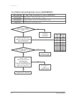
Page 106: ...t data display part Check the temp data is normal or not after pressing K4 2 times At this time is occurred the difference between the out temp and data Reoperation after PCB replacement Does the out heat exchanger temp sensor connected to PCB CN41 At this time Is largely deviate the resistance value from side table value Temp C 70 60 50 40 30 20 10 0 10 Resistance kΩ 2 2 3 0 4 2 5 8 8 3 12 1 18 0...

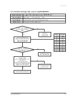
Page 107: ...time Is largely deviate the resistance value from side table value Measure the resistance value between two terminals after separating the outdoor discharge temp sensor connector from PCB Temp C 130 120 100 80 60 25 20 10 0 Resistance kΩ 8 9 11 2 18 5 32 59 200 242 362 553 PCB and sensor are normal To perform the test operation by use of K2 No No Outdoor heat exchanger temp is defective replace Ye...

Page 108: ... then replace the indoor unit PCB after line check Check the display after pressing the reset key on outdoor PCB When tracking is there any indoor answer from display part At this time is the voltage between lines rectangular wave over DC 0 7V like below figure 0 7V 0 7V Good Bad Multi type After 2 minutes check if PCB address setting of indoor unit displayed the communication error among indoor u...

Page 109: ...PCB and actual indoor unit installation numbers To measure the 2 lines of outdoor unit side by use of scope after removing the communication line connecting from outdoor unit to indoor unit Is equal indoor unit actual installation number and installation number setting switch At this time is the voltage between lines rectangular wave over DC 0 7V When tracking is there any indoor answer from displ...

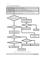
Page 110: ...rminal after taking out the floating switch connector connected to indoor unit PCB Open status Is much the water of drain pan Does the drain pump operate Does the water level decrease Is the same error occurred Is the terminal voltage of drain pump PCB about AC220V Re assembly the floating switch connector and perform the reset of outdoor power Required the reset of indoor unit power No Outdoor un...

Page 111: ...fy the resistance value in accordance with temperature 4 Is the resistance value of sensor connection pull_up correct 2 Troubleshooting procedure Isn t the Fan locked Is the color of Fan wire matched correctly Remove the Fan lock Connect the connector Exchange the Fan Exchange the PCB Normal operation Exit Is the connector connected correctly No No No No Yes Yes Yes ...

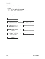
Page 112: ...g procedure Restart after power off Is the restart error occurred again Is the interphase resistance value of com pressor U V V W W U normal Is the connection cable for thecompressor and power terminal normal Exchange the PCB Terminate the service Exchange the compressor Is the compressor body and interphase resis tance insulated Exchange the compressor Correct the cable connection Yes Yes Yes Yes...

Page 113: ...g procedure Restart after power off Is the lock error occurred again Is the interphase resistance value of com pressor U V V W W U normal Is the connection cable for the compres sor and power terminal normal Exchange the PCB Terminate the service Exchange the compressor Is the compressor body and interphase resistance insulated Exchange the compressor Correct the cable connection Yes Yes Yes Yes N...

Page 114: ...heck the voltage of No 15 and No 16 of the main PCB CN91 while operating the remote control When the voltage descends below 3V the assembly module PCB is normal and the main PCB is poor Then replace the main PCB 3 Replace the assembly display PCB because the module PCB is poor if the voltage between No 15 16 of CN91 maintains 5V after the remote control starts operation ...

Page 115: ...ICOM Room Temperature Pipe Temperature Sensor Control part Option Saving Part EEPROM Ventilator Control Indoor Fan BLDC Outdoor Fan Control TAP No of Indoor Setting S W MICOM 3 Phase Check part Room Temperature Pipe Temperature Sensor Control part Sensor Control Part 13 2 Outdoor Unit CCH 4 Way Valve Compressor Outdoor Fan 3 Phase Input Room Pipe Discharge Temperature Sensor Display Control Part O...

Page 116: ...ly Normal N H 115V 60Hz A 220V 60Hz B TB 208 230V 60Hz C 200 220V 50Hz D 220 240V 50Hz E TE 220V 60Hz 3Φ F TF 380 415V 50Hz 3Φ G TG 127V 50Hz H 220 240V 50 60Hz 1Φ M 380V 60Hz 3Φ H Inverter 1Φ V Inverter 3Φ W Plant SEC None SSEC C TSE T Refrigerant R 22 Z R407C C R410A A Mode C O C H P H H P Heater E C O Heater G C O Hydronic N Product Type ll Normal Indoor A Outdoor X Universal DPM Indoor M Outdo...

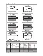
Page 117: ... Cooling Low Pressure 2 4 0 6 8 10 5 21 35 43 7 5m 50m Outdoor Air Temp C CH052 070EAMC UH052 070EAMC m c g k e r u s s e r P g Cooling Low Pressure 2 4 0 6 8 10 5 21 35 43 7 5m 50m Outdoor Air Temp C CH105EAMC UH105GAMC CH140EAMC UH140GAMC m c g k e r u s s e r P g Heating High Pressure Heating High Pressure Heating High Pressure 10 20 0 30 40 50 10 20 0 30 40 50 10 2 7 24 7 5m 50m Outdoor Air Te...

Page 118: ...t floods the floor A Place the drain hose properly When it is not placed properly the drain water would flow back flooding the floor So straighten out the drain hose for the water to be drained well Q Water drips at the drain connection service valve of the outdoor unit A When a glass bottle is taken out of the refrigerator moisture gets condensed on its surface due to the temperature differences ...

Page 119: ...urs generally when there are pet animals in the house Their smells stay at the same place But when the air conditioner is turned on the air gets circulated resulting in the circulation of the smells So find and root out the problem or refresh the room frequently Q It sends out bad smells A When the air filter is filthy it could send out bad smells So clean the filter and ventilate the room with th...

Page 120: ...se with the outdoor unit in it outside the apartment Also it is illegal obstructing passers by with the outdoor unit installed outside Q What can be done to install the outdoor unit facing the road because it is a commercial build ing A The following is an excerpt from Building Code going into effect from JUNE 1st 2005 The exhaust pipe of a cooling or ventilation facility installed in a building a...

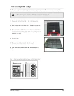
Page 121: ...ll dust on air filter with a vacuum cleaner or a brush In case of serious dust accumulation put the air filter in warm detergent water and shake it vertically 4 Dry the air filter 5 When you have finished insert the filter into the unit 6 Clean the outdoor unit with a vacuum cleaner or a brush once a month Note After cleaning the air conditioner press the Filter Reset button Before cleaning your a...

Page 122: ... torque wrench to tighten pipes or flare nuts Leak Test Put an inert gas like nitrogen in the outdoor unit pipe and put soap bubbles or other test liquids on the pipe surface for the leak test Drain Hose Connecting Install the drain hose downward to drain water naturally Be sure to pour water into the hose to check if it drains well Testing Drainage Pure water into the drain pan in the indoor unit...

Page 123: ...he valve of the low pressure side of manifold gauge clockwise Remove the hose of the low pressure side of manifold gauge 7 Check for gas leakage At this time especially check for gas leakage from the 3 way valve s stem nuts and from the service port cap 2 Connect the charging hose of low pressure side of manifold gauge to the packed valve having a ser vice port as shown at the figure 5 Set valve c...

Page 124: ...alve 2 way Valve Relocation of the air conditioner Refer to this procedure when the unit is relocated Carry out the pump down procedure refer to the details of pump down Remove the power cord Disconnect the assembly cable from the indoor and outdoor units Remove the flare nut connecting the indoor unit and the pipe At this time cover the pipe of the indoor unit and the other pipe using a cap or vi...

Page 125: ...Samsung Electronics 14 10 MEMO ...

Page 126: ...onics Co Ltd July 2007 Printed in China Code No DB98 26327A 4 Area Web Site North America http service samsungportal com Latin America http latin samsungportal com CIS http cis samsungportal com Europe http europe samsungportal com China http china samsungportal com Asia http asia samsungportal com Mideast Africa http mea samsungportal com GSPN Global Service Partner Network ...

Reviews: