background image

4-5. RS-232C

RS232C Control

• 

 Port : COM#(Serial)


-

 Bit rate : 115200


-

 Data Bit : 8 bit


-

 Parity : None


-

 Stop Bits : 1


-

 Flow Control : None


-

Description of RS232C

• 

Pin# Name

Full Name

Pin# Name

Full Name

Pin# Name

Full Name

1

CD

Carrier Detect

4

DTR

Data Terminal Ready

7

RTS

Request To Send

2

RxD

Received Data

5

GND

Signal Ground

8

CTS

Clear To Send

3

TxD

Transmitted Data

6

DSR

Data Set Ready

9

RI

Ring Indicator

4-46 

4. Troubleshooting

Summary of Contents for UN HU7250F Series

Page 1: ...UHD TV SERVICE Manual UHD TV Contents 1 Precautions 2 Product specifications 3 Disassembly and Reassembly 4 Troubleshooting 5 Wiring Diagram UN HU7250F Chassis U8JD Model UN55HU7250F UN65HU7250F ...

Page 2: ...the Panel 2 10 2 4 3 Motion Control 2 14 3 Disassembly and Reassembly 3 1 3 1 Disassembly and Reassembly 3 1 3 1 1 Set Disassembly 3 1 4 Troubleshooting 4 1 4 1 Troubleshooting 4 1 4 1 1 Previous Check 4 1 4 1 2 Simple flow chart of malfunction 4 3 4 2 How to Check Fault Symptom 4 4 4 2 1 No Power 4 4 4 2 2 No Video HDMI 1 2 3 4_Digital signal 4 7 4 2 3 No Video Tuner_CVBS 4 10 4 2 4 No Video Tune...

Page 3: ...4 5 RS 232C 4 46 4 6 AV Control Tabe 4 47 4 7 Updating the TV s Software 4 53 5 Wiring Diagram 5 1 5 1 Wiring Diagram 5 1 5 2 Connector 5 3 5 3 Connector Functions 5 7 5 4 Cables and Module 5 8 ...

Page 4: ...anual is a property of Samsung Electronics Co Ltd Any unauthorized use of Manual can be punished under applicable International and or domestic law 2014 Samsung Electronics Co Ltd All rights reserved Printed in Korea ...

Page 5: ...nents 3 1 Disassembly and Reassembly CAUTION Disconnect the LED TV from the power source before disassembly 1 Follow these directions carefully never use metal instruments to pry apart the cabinet 2 If there is no additional coment it is same for all inches 3 3 1 1 Set Disassembly Description Picture Description Screws 1 Place TV face down on cushioned table 2 Remove 4 screws from the ASSY GUIDE P...

Page 6: ...screws from the ASSY COVER P REAR 55 inches 21EA 2EA 65 inches 21EA 2EA Torque 7 8Kgf cm 6001 002755 Torque 9 11Kgf cm 6003 001782 Remove the ASSY COVER P REAR 5 Remove the all cables Speaker Cable Power Cable Power Cable Panel Drive Cable LVDS Cable 6 Remove the ASSY SPEAKER P L R ...

Page 7: ... inches 6 EA Torque 7 8Kgf cm 6001 003016 8 Remove screws from the DC VSS LED TV PD BD 55 inches 7 EA 65 inches 7 EA Torque 7 8Kgf cm 6001 003016 9 Before removing the 1 NET WORK WIFI MODULE 2 ASSY BOARD P RF MODULE cable and remove the screws 2 ASSY BOARD P RF MODULE 1 NETWORK WIFI MODULE 1 NETWORK WIFI MODULE Remove the cable ...

Page 8: ...ription Picture Description Screws 2 ASSY BOARD P RF MODULE Remove the cable 10 Remove the screws T con Board Torque 7 8Kgf cm 6001 003016 Remove the T CON cable NOTE Reassembly procedures are in the reverse order of disassembly procedures ...

Page 9: ...obs insulating materials cabinet backs adjustment and 2 compartment covers or shields isolation resistorcapacitor networks mechanical insulators etc Leakage Current Hot Check 3 DEVICE UNDER TEST READING SHOULD NOT BE ABOVE 0 5mA LEAKAGE CURRENT TESTER TEST ALL EXPOSED METAL SURFACES 2 WIRE CORD ALSO TEST WITH PLUG REVERSED USING AC ADAPTER PLUG AS REQUIRED EARTH GROUND WARNING Do not use an isolat...

Page 10: ...ed by replacing them with components rated for higher voltage wattage etc Parts that have special safety characteristics are identified by on schematics and parts lists A substitute replacement that does not have the same safety characteristics as the recommended replacement part might create shock fire and or other hazards Product safety is under review continuously and new instructions are issue...

Page 11: ... used 2 The internal wiring is sometimes clamped to prevent contact with thermally hot components Reinstall all such elements to their original position After servicing always check that the screws components and wiring have been correctly reinstalled Make sure that 3 the area around the serviced part has not been damaged Check the insulation between the blades of the AC plug and accessible conduc...

Page 12: ...s sufficient to damage ESDs 3 Use only a grounded tip soldering iron to solder or desolder ESDs 4 Use only an anti static solder removal device Some solder removal devices not classified as anti static can generate 5 electrical charges sufficient to damage ESDs Do not remove a replacement ESD from its protective package until you are ready to install it Most replacement ESDs 6 are packaged with le...

Page 13: ...antenna far away from any high voltage cables and install it firmly Contact with the highvoltage cable or the 6 antenna falling over may cause fire or electric shock When installing the product leave enough space 0 4m between the product and the wall for ventilation purposes 7 A rise in temperature within the product may cause fire If an equipment is provided with a replaceable battery and if repl...

Page 14: ... 4 mm With Stand 48 5 x 29 9 x 11 6 inches 1233 0 x 760 4 x 294 9 mm 65 Without Stand 57 1 x 33 0 x 5 2 inches 1451 2 x 839 9 x 134 6 mm With Stand 57 1 x 34 6 x 11 7 inches 1451 2 x 881 0 x 298 5 mm Weight 55 Without Stand 41 6 lbs 18 9 kg With Stand 48 0 lbs 21 8 kg 65 Without Stand 61 7 lbs 28 0 kg With Stand 69 8 lbs 31 7 kg Panel Type Black Internal Memory 4G DDR 2G Feature Instant On TTS Zoo...

Page 15: ...hes LCD Panel UHD 60Hz Scanning Frequency Horizontal 60 136kHz Vertical 56 75Hz Display Colors 1 07B Display Resolution 3840 x 2160 Input Signal RGB Analog 0 7 Vp p 5 positive at 75Ω internally terminated Input Sync Signal H V Separate TTL P or N Maximum Pixel Clock Rate 138MHz AC Power Voltage Frequency AC110 120V 60Hz Environmental Considerations Operating Temperature 50 F 104 F 10 C 40 C Operat...

Page 16: ... Black Local Dimming N A Wide Color Enhancer Plus Yes Color Accuracy N A Auto Depth Enhancer No Auto Motion Plus 120HzHz Film Mode Yes Audio Dolby MS10 MS110 MS11 DTS Studio Sound DNSe DTS Studio Sound DTS Premium Sound DTS Premium Sound 5 1 DTS Premium Sound 5 1 3D Sound N A Auto Volume Leveler Yes Sound Customizer No Sound Output RMS 20W Left 10W Right 10W Speaker Type Down Firing Woofer N A HD ...

Page 17: ...HDMI 4 USB 3 Component In Y Pb Pr 1 Composite In AV 2 1Common Use for Component Y Ethernet LAN Yes Headphone No Audio Out Mini Jack Yes Digital Audio Out Optical 1 PC In D sub N A PC DVI Audio In Mini Jack N A RF In Terrestrial Cable input 1 1 Common Use for Terrestrial 0 Ex Link RS 232C 1 One Connect Jack Yes WiFi Direct Yes MHL Yes Wireless LAN Built in Yes Anynet HDMI CEC Yes Design Design T sh...

Page 18: ... Picture Yes Multi Tasking Yes BT HID Built in Yes USB HID Support Yes Smart Evolution Support Yes TV SoundConnect Yes Teletext TTXT No Time Shift No V Chip Yes Eco Feature Eco Label Energy Star 6 1 Eco Sensor Yes Accessory 3D Active Glasses Included N A Remote Controller Model TM1460A Batteries for Remote Control Yes Samsung Smart Touch Control Included Yes Ultra Slim Wall Mount Supported N A Min...

Page 19: ...2 6 2 Product specifications Item UN HU7250FXZA Accessory Slim Gender Cable N A ...

Page 20: ... The part code for some accessories may differ depending on your region The provided accessories may vary depending on the model Product Code No Product Code No Samsung Smart Control BN59 01185F User Manual BN68 06542A Batteries AA x 2 4301 000101 Regulatory guide BN68 04972A Power Cord 3903 000853 Image Product Code No IR Extender Cable BN96 31644A Wall Mount Adapter BN61 07295A ...

Page 21: ...sing your voice Changes channels Adjusts the volume Touch pad Place a finger on the touch pad and move the Samsung Smart Control The pointer on the screen moves in the direction you moved the Samsung Smart Control Press the touch pad to run the focused item Press and hold the touch pad to display the Context Sensitive Menus Moves the cursor selects the on screen menu items and changes the values s...

Page 22: ... cursor in the direction you want To enter a menu or select an item highlight the item or the menu title or move the pointer over it and then press the touch pad Displaying Context sensitive Menus in Smart Hub Changing the Smart Hub Panel In Smart Hub highlight an item and then press and hold the touch pad The context sensitive menu for the item pops up The context sensitive menu may vary dependin...

Page 23: ...anel you must be logged in to your Samsung Account SAMSUNG APPS Panel Smart Hub offers a variety of free news sports weather and gaming apps you can install directly to and enjoy on your TV The first line on the screen contains apps recommended by Samsung These apps were automatically downloaded to your TV when you set up Smart Hub The lines of apps below the first line contain some apps that were...

Page 24: ...rom the actual channels or programs depending on the broadcast information provider You can automatically launch On TV when the TV is turned on Navigate to Smart Hub On TV Settings and set Auto Start to On You can use the following features by selecting the buttons at the bottom of the screen Viewing the Program Schedule of Digital Channels Select Guide at the bottom of the screen to view the prog...

Page 25: ... MOVIES TV SHOWS options may not be available depending on the content you are trying to access or your region The TV must be connected to the Internet for you to use MOVIES TV SHOWS Select on the screen to change the recommended content list Multimedia Panel Playing Photos Videos and Music The Multimedia Panel lets you play media content saved on USB devices smartphones cameras computers or in St...

Page 26: ...pdated in real time NewsON brings you the latest headlines top stories popular issues and weather forecasts SOCCER Panel The SOCCER panel offers a variety of information about world soccer matches featuring videos news matchups and ratings Adding a favorite team to the Favorite list allows easy access to information about team Before you use the SOCCER panel check if the TV is connected to the Int...

Page 27: ...ilable for the selected item Zooming the picture on the screen in or out Facing the camera raise both hands and then raise the index finger on both hands Two pointers appear on the screen when the TV recognizes the hands Fold the index fingers of both hands down and then horizontally widen or close your hands This lets you zoom the picture on the screen in or out when the TV is displaying a web pa...

Page 28: ... ASSY DECORATION SMT ASSY SPEAKER P R L How to distinguish if the problem is caused by 3 Main Board or T CON No Video If the problem is No Video but BLU is on and Indication LED is blinking repeatedly and faster than nomal booting replace the T CON board Distorted Picture Check the inner patterns For All mode NT14U NT72323BG FRC Picture Problem OK OK NG Main Board or Signal Source NG OK NG Main Bo...

Page 29: ...tern Enter Service Mode 2 If you do not have Factory remote control Power OFF MUTE 1 8 2 Power On If you have Factory remote control INFO Factory Choose SVC 3 Test pattern Option Control Debug SVC ADC WB Advanced Test Pattern Test Pattern Sel Check inner patterns 4 4 2 4 Troubleshooting ...

Page 30: ... broadcast No Replace the Main Board Yes No No Yes Yes Check the LVDS Cable connected If necessary replace the T CON Board No Change the Main Board No Check 24P Cable If necessary replace the SMPS Board Yes No Change the Main Board Does the TV turn on Check the Power Cord Is any sound of TV when RF signal connected A5V appear at the pin 4 of CN201 B13V appear at the pin 11 12 13 of CN201 Please co...

Page 31: ...the unit Check the fuses of each part Check the output voltage of SMPS Replace the Main Board Diagnostics Power indicator LED is on No Check a connetion power code Yes Check the backlight on when 24P cable unconnected No Replace 24P Power Cable Replace Main Power Ass y Yes 1 Check Stand By 5V BD213 A5 3V No Yes 1 Check Power input of Main Ass y BD206 BD208 B13VS BD200 BD205 B13V BD228 B5V No Yes 2...

Page 32: ...ck Power of T con Board CD220 T CON VIN_12V BT1 T CON VCC_1 15V No Change the T con Board Yes Please Contact tech support Caution Make sure to disconnect the power before working on the IP board 4 5 4 Troubleshooting ...

Page 33: ...Location of Parts Main Board_Front 1 2 4 3 Detail 1 BD228 B5V BD206 BD208 B13VS BD200 BD205 B13V BD213 A5 3V 2 BD300 BD302 C0 95V IC210 A3 3V BD304 C1 5V 3 L202 C3 3V 4 L200 C5V 4 6 4 Troubleshooting ...

Page 34: ... at Input of Main Board HDMI1 Clk Pin 10 12 of CN700 DATA Pin 7 9 4 6 1 3 of CN700 HDMI2 Clk Pin 10 12 of CN701 DATA Pin 7 9 4 6 1 3 of CN701 HDMI3 Clk Pin 10 12 of CN801 DATA Pin 7 9 4 6 1 3 of CN801 HDMI4 Clk Pin 10 12 of CN800 DATA Pin 7 9 4 6 1 3 of CN800 No Check CN700 701 800 801 Check HDMI cable Change the Main Ass y or Check IC1400 NT14U Change the Main Ass y Yes 2 Check the LVDS clk signa...

Page 35: ...Location of Parts Main Board_Front 2 HDMI3 HDMI2 HDMI1 HDMI4 1 Detail 1 CN801_H3 CN701_H2 CN700_H1 CN800_H4 2 4 8 4 Troubleshooting ...

Page 36: ...Waveforms 1 HDMI input RX_Data RX_Clk 2 LVDS output 4 9 4 Troubleshooting ...

Page 37: ...F cable No Input the RF source properly Yes 1 Check the Power of Tuner Pin 4 of Tuner B1 8V_Tuner Pin 1 of Tuner B3 3V_Tuner No Change the Main Ass y Yes 1 2 Check the CVBS data out of IC1400 L903 Tuner CVBS_OUT CVBS_OUT_TP IC1400 CVBS_ OUT No Check IC1400 NT14U Change the Main Ass y Yes 3 Check the LVDS clk signal at output of Main Board TX TX6_CLK TCON SDA TX8_DATA TCON SCL No Check IC1400 NT14U...

Page 38: ...Location of Parts Main Board_Front 2 Tuner 1 3 Detail 1 Pin 4 B3 3V Pin 1 A3 3V L903 TUNER CVBS OUT 2 CVBS_OUT_TP IC1400 CVBS OUT 3 4 11 4 Troubleshooting ...

Page 39: ...Waveforms 1 CVBS OUT Grey Bar 3 LVDS output 4 12 4 Troubleshooting ...

Page 40: ...connection of RF cable No Input the RF source properly Yes Check the signal strength in Self Diagnosis menu Strength is enough No Check the DTV source Yes 1 Check the Power of Tuner Pin 4 of Tuner B1 8V_Tuner Pin 1 of Tuner B3 3V_Tuner No Change the Main Ass y Yes 2 Check the LVDS clk signal at output of Main Board TX TX6_CLK TCON SDA TX8_DATA TCON SCL No Check IC1400 NT14U Change the Main Ass y Y...

Page 41: ...Location of Parts Main Board_Front Tuner 1 2 Detail 1 Pin 4 B3 3V Pin 1 A3 3V 2 4 14 4 Troubleshooting ...

Page 42: ...Waveforms 2 CH_CLK CH_VALID 2 CH_CLK CH_VALID 3 LVDS output 4 15 4 Troubleshooting ...

Page 43: ...cklight on no video No Check a set in the Stand by mode Yes Check the video source and check the connection of video cable No Input the video source properly Yes 2 Check the LVDS clk signal at output of Main Board TX TX6_CLK TCON SDA TX8_DATA TCON SCL No Check IC1400 NT14U Change the Main Ass y Yes Check the LVDS cable Replace the T CON LCD panel Yes Please Contact tech support Caution Make sure t...

Page 44: ...Location of Parts Main Board_Front 1 2 Detail 1 R1019 C1011 COMP2_Y_CVBS 2 4 17 4 Troubleshooting ...

Page 45: ...Waveforms 1 CVBS OUT Grey Bar 3 LVDS output 4 18 4 Troubleshooting ...

Page 46: ...he component source and check the connection of component cables Y Pb Pr No Input the component source properly Yes 1 2 Does the component data appear at COMP2_Y_CVBS R505 Pb R504 Pr R502 No Check CN502 Change the Main Ass y Yes 3 Check the LVDS clk signal at output of Main Board TX TX6_CLK TCON SDA TX8_DATA TCON SCL No Check IC1400 NT14U Change the Main Ass y Yes Check the LVDS cable Replace the ...

Page 47: ...Location of Parts Main Board_Front 1 2 Detail 1 R816 COMP2_Y_CVBS R504 COMP2_PB R502 COMP2_PR 2 4 20 4 Troubleshooting ...

Page 48: ...Waveforms 1 Compnent_Y Gray scale Pb Pr Color bar 1 Compnent_Y Gray scale Pb Pr Color bar 2 LVDS output 4 21 4 Troubleshooting ...

Page 49: ... the signal at input of Main Board AV COMP L R R520 No Check CN502 Change the Main Ass y Yes 2 Check the DATA between the Audio IC s Pin 15 of IC500 Bclk Pin 20 of IC500 LRclk Pin 23 24 of IC500 I2C_SDA SCL No Check IC500 Change the Main Ass y Yes 3 4 Check the Speaker sound data at 1 CN400 Check the Monitor out sound data at 2 CN2101_IBR Does the SODIF OUT sound data 3 appear at OP400 No Check IC...

Page 50: ...arts Main Board_Front 1 4 2 CN400 3 Detail 1 R520 Bottom side COMP2_AV2_SR_IN 2 Pin 20 LRclk Pin 23 24 I2C_SDA SCL Pin 15 Bclk 3 CN401 Speaker jack 4 OP400 Optical CN2101_IRB Monitor out_Sound 4 23 4 Troubleshooting ...

Page 51: ...Waveforms 1 MCLK LRCLK PCM_I2C_DATA 1 MCLK LRCLK PCM_I2C_DATA 2 Speaker Monitor OUT SPDIF OUT 2 Speaker Monitor OUT SPDIF OUT 4 24 4 Troubleshooting ...

Page 52: ... SDC SDC Code BN95 01798A BN95 01799A Spec CY VH055FGLV1V CY VH065FGLV1V SMPS BOARD Vendor HANSOE HANSOE Code BN44 00781A BN44 00782A Spec L55C4_EHS L65C4_EHS MAIN BOARD Chassis Ass y BN91 13411A BN91 13411B PBA Ass y BN94 07777A BN94 07777B Byte Item 0 Factory Reset 1 Type 55A1UU7RH 65A1UU7RH 2 Local set US US 3 SW Model UHU7250 UHU7250 4 BOM Model 7250 7250 5 Tuner S_TC S_TC 6 Ch table NONE NONE...

Page 53: ...D SUCCESS CALIB AV COMP PC HDMI Option xxxx US 72xx NONE DTP SDAL NT14U ATSC xxxx xxxx RFS NT14U 0166 K 0 201x xx xx KERNEL 159 1250 Onboot 0100 1 DTP DTVTD 4631 0028 Backend NT72324 FW 0xx Ldc 0xx TCON Version Model UN55HU72xx Wired MAC SUCCESS Wireless MAC SUCCESS WIFI ATH6KL 5 0 0 99_0522 CO Nf W M D HO PO AO S N Factory Data Ver 220 EERC Ver 97 SmartControl xxxx DTP BP HAL 4631 NT14U_ATSC 016 ...

Page 54: ...EIDA Language_Arabic US Region PANEURO PnP Language ENG WIFI REGION E OTN Support ON OTA Support General MediaPlay DLNA TTX ON China HD OFF NT Conversion OFF Num of DTV DECODER 2 Num of AV 2 Num of COMP 1 Num of HDMI 4 Num of SCART 0 Num of USB Port 3 Num of USB 3 0 1 Num of RVU 1 Num of Display 2 Num of IPTV 0 Num of RUI 0 Num of PVR RECORD 0 TOOLS Support 104 LNA Support OFF 4 27 4 Troubleshooti...

Page 55: ...V Flip FRC HV Flip Light Effect OFF e Pop Default ON CAMERA Support OFF NETWORK Support Int Wifi EcoSensor Support ON 3D Support OFF BT Support ON BT ADDRESS 508569b1285e HP LINE Smart Control Support ON Motion Recog ON Voice Recog ON Virtual Remocon Color 1 Local Dimming Panel OFF Wifi Vendor QCA Engineer Option Type Of PANEL KEY None 5 Way Function Key R BACK Contents Bar OFF Cable Modulation QA...

Page 56: ...ING_PSI_UPDATE ECO Standby OFF Fast Logo Delay 0 Num of PANEL KEY 6 Panel Detail 0 Panel Init Time 250 Tcon Init Time 460 WRITE MAC Address Control Factory Menu Name Data Range EDID EDID ON OFF OFF EDID WRITE ALL EDID WRITE HDMI EDID Ver EDID Port Sub Option RS 232 Jack UART Serial Log On Off OFF Watchdog OFF FRC Monitoring OFF Checksum 0x0000 Fast Boot in Production OFF 4 29 4 Troubleshooting ...

Page 57: ...Server OFF SWU Reset SWU Duration OFF SWU Fail Test OFF OPTION_NUM Num of ATV 1 Num of SVIDEO 0 Num of PC 0 Num of DVI 0 Num of OPTICAL Link 1 Num of MEDIA 1 Num of Tuner 1 Num of ISP 1 Num of HDMI SW 1 Num of SII9679 1 RF Remocon Support OFF CDD mode DPMS Support OFF Num of IPTV CIP 0 Num of CI 0 Num of HYBRID TV 0 T CON Device BOARD CONTROL OFF RM Server Type Operating RTS Mode OFF PSA 4 30 4 Tr...

Page 58: ...Fanet Thread 2 ACM_MC OFF Support MiniBrowser OFF HotkeyList 7K_NON_3D PDP Option Pixel Shift Test OFF Logic SW 0 Panel Temperature 0 LOGIC Waveform Day 0 Logic CheckSum 0 MRT 0 SAPC Timer APC Speed Hotel Option Hospitality Mode OFF Power On MyChannel Menu OSD Operation Music Mode External Source Eco Solution Cloning Shop Option Shop Mode OFF Exhibition Mode OFF 4 31 4 Troubleshooting ...

Page 59: ...escale 0x48h BTSC Mono Prescale 15 BTSC stereo Prescale 29 BTSC SAP Prescale 29 A2Ident High THID 36 A2Ident Low THID 9 Pilot Level High Thld 0x0Fh Pilot Level Low Thld 0x08h Carrier2 Amp High THID 4 Carrier2 Amp Low THID 3 Carrier2 SNR High THR 16 Carrier2 SNR Low THR 80 Sig Error On 35 Sig Error Off 41 Amp Model TAS5745 Amp Volume 0xc9h Amp Scale 0x35h Amp Check Sum 0x00F95FB3 Woofer Type 0 Woof...

Page 60: ...nx 2 Lipsync CheckSum NG 0x5248 Lipsync USB Test Ready Lipsync BT CheckSum OK 0x0000 Debug Factory Menu Name Data Range Spread Spectrum LVDS Spread OFF DDR Spread ON Period 20K Amplitude 0 1 HD SSC ON Off OFF HD SSC Value 1 LVDS SSC ON Off OFF LVDS SSC Value 0 DDR SSC ON Off OFF DDR SSC Value 1 FRC Vx1 SSC ON OFF ON FRC LVDS SSC ON OFF OFF FRC LVDS SSC MFR 1 FRC LVDS SSC Period 0 FRC LVDS SSC Modu...

Page 61: ...ime 6ms CI 1 3 OFF FRC FRC FDISPLAY ON OFF 0 3D FDISPLAY ON OFF OFF PC Mode ON OFF OFF Home Panel FRC OFF DDR Test OFF Tuner Margin 10 MPEG Margin 100 H 264 Margin 100 CAM Wait Time TS Clock deldy 0 TCON_TEMP READ 0 TEMP LAST 60 DCC VERSION 0x0 DCC CHK SEL 0 DCC CHECK LOCAL 0x0 DCC CHECK TOTAL 0x0 MulitACC Checksum 0 IIC Bus stop OFF Tuner Status DVB SNR BER Signal Strength Bandwidth Frequency 4 3...

Page 62: ...D Type TPS Lock RS Lock SSI SQI Firmware Version ISDB T FFT Size_1 Guard Interval_1 Freq Offset_1 SNR_1 IF AGC_1 TMCC Lock_1 TS Packet_1 Master Lock_1 A_Modulation_1 A_Code Rate_1 A_Timer InterLeave_1 A_Segments Num_1 A_BER_1 B_Modulation_1 B_Code Rate_1 B_Timer InterLeave_1 B_Segments Num_1 B_BER_1 C_Modulation_1 4 35 4 Troubleshooting ...

Page 63: ...p Back OFF LAN Test AV Audio Test AV2 Audio Test DVIN Audio Test CVBS Test CVBS2 Test COMP Test USB HUB Test HDMI Test SCART Audio Test SCART CVBS Test SCART RGB Test PC Audio Test PC Self Test CPU DDR FLASH EEPROM HDMI Switch IC USB HUB IC WIFI LVDS T CON FRC PCB Test MOIP App Self Test Device Self Test Voltage 4 36 4 Troubleshooting ...

Page 64: ...g View 0 Delete Log Debug Log Down RM log transmission OFF ER Count WD Count 0 Power Fail Count 236 AR Count 0 WIFI ER Count 0 WIFI NO DETECTION COUNT 0 WIFI DETACCHMENT COUNT 3 BT ER Count 0 BT NO DETECTION COUNT 0 BT DETACHMENT COUNT 0 BT MGT OPEN FAIL COUNT 0 BT MGT DISCONNECT COUNT 1 Camera ER Count 0 FRC3D Reboot On Off ON FRC3D ER Count 0 Panel Display Time 24Hr Factory Entry Number 18 Facto...

Page 65: ...M UPGRADE Failure Jump Upgrade Failure IR Blaster Upgrade Failure IR Blaster delay time 50 CPLD Download LDC PROFILE UPGRADE Failure Pic Data USB Update 0 Audio Data USB Update 0 Eco Data USB Update VER 0x0006 SC ADK Upgrade Failure SC MBR Upgrade Failure Reset Apps Reset 0 EEPROM Rst 0 SPI Flash Reset Success OPTION_HDMI DVI HDMI SOUND HDMI HOT PLUG HOTPLUG SWITCHING HOT PLUG DURATION 1200ms CLK ...

Page 66: ...ilure SPI VERSION 0x2025 DVB CI TS Clock delay TC 0 TS Clock delay S 0 CI Control Buf On ON TS Clock delay CPU 1 Test Pattern Pattern Sel OFF Logic Pattern Sel Logic Level Sel FRC Pre Test Pattern 0 FRC Post Test Pattern 0 SOC TCON Test Pattern 0 SOC TCON Pattern Level 255 SOC TCON FRC Pattern 0 HDMI WB Pattern OFF HDMI Pattern Sel 0 Parma Pre Test Pattern 0 Parma Post Test Pattern 0 FRC OSD PRE P...

Page 67: ...INAL ADC WB Factory Menu Name Data Range ADC AV Calibration Comp Calibraion PC Calibration HDMI Calibration ADC Result 1st_Y_GH 1st_Y_GL 1st_Cb_BH 1st_Cb_BL 1st_Cr_RH 1st_Cr_RL 2nd_R_L 2nd_G_L 2nd_B_L 2nd_R_H 2nd_G_H 2nd_B_H White Balance R Offset G Offset B Offset R Gain G Gain B Gain WB_W2_R_Offset WB_W2_B_Offset 4 40 4 Troubleshooting ...

Page 68: ...Gain WB_N_B_Gain MGA MGA On Off OFF R1_Gain G1_Gain B1_Gain R2_Gain G2_Gain B2_Gain R3_Gain G3_Gain B3_Gain R4_Gain G4_Gain B4_Gain R5_Gain G5_Gain B5_Gain R6_Gain G6_Gain B6_Gain R7_Gain G7_Gain B7_Gain R8_Gain G8_Gain B8_Gain R9_Gain G9_Gain B9_Gain R10_Gain G10_Gain 4 41 4 Troubleshooting ...

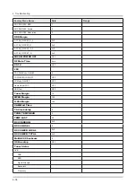
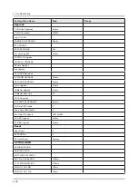
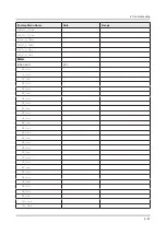
Page 69: ...Factory Menu Name Data Range B10_Gain Advanced 4 42 4 Troubleshooting ...

Page 70: ... Adjust Specification Source Setting Mode Pattern Use Equipment HDMI 1280 x 720 60 Hz Pattern 24 Chess Pattern CA210 Master MSPG925 Generator Chess Pattern Use other equipment only after comparing the result with that of the Master equipment Input mode Calibration Pattern CVBS IN Model_ 1 Perform in NTSC B W Pattern 24 Lattice Component IN Model_ 6 Perform in 720p B W Pattern 24 Lattice PC Analog ...

Page 71: ...h level menu 7 You can see the change of the Comp Calibration status from Failure to Success 8 Method of Color Calibration PC Apply the VESA XGA Lattice N0 21 pattern signal to the PC IN port 1 Press the Source key to switch to PC mode 2 Enter Service mode 3 Select the ADC menu 4 Select the PC Calibration menu 5 In PC Calibration Off status press the key to perform Calibration 6 When Calibration i...

Page 72: ...y Mode 1 Select 2 ADC WB menu Select 3 White Balance menu Option Control Debug SVC ADC WB Advanced White Balance Low Light Sub Brightness R offset G offset B offset Hight Light Sub Contrast R gain G gain B gain 4 45 4 Troubleshooting ...

Page 73: ...ontrol None Description of RS232C Pin Name Full Name Pin Name Full Name Pin Name Full Name 1 CD Carrier Detect 4 DTR Data Terminal Ready 7 RTS Request To Send 2 RxD Received Data 5 GND Signal Ground 8 CTS Clear To Send 3 TxD Transmitted Data 6 DSR Data Set Ready 9 RI Ring Indicator 4 46 4 Troubleshooting ...

Page 74: ...d2 Cmd3 Value Input Source List TV TV 0x0a 0x00 0x00 0x00 AV AV1 0x01 0x00 AV2 0x01 AV3 0x02 S Video S Video1 0x02 0x00 S Video2 0x01 S Video3 0x02 Component Component1 0x03 0x00 Component2 0x01 Component3 0x02 PC PC1 0x04 0x00 PC2 0x01 PC3 0x02 HDMI HDMI1 0x05 0x00 HDMI2 0x01 HDMI3 0x02 HDMI4 0x03 DVI DVI1 0x06 0x00 DVI2 0x01 DVI3 0x02 Control Item Cmd1 Cmd2 Cmd3 Value PICTURE Mode Dynamic Entert...

Page 75: ...1 Darker 0x02 Darkest 0x03 Dynamic Contrast Off 0x01 0x00 Low 0x01 Medium 0x02 HIgh 0x03 Shadow Detail 2 2 0x02 2 2 Gamma 3 3 0x03 3 3 RGB Only Mode Off 0x05 0x00 Red 0x01 Green 0x02 Blue 0x03 Color Space Auto 0x06 0x00 Native 0x01 Custom 0x02 White Balance R Offset LCD 0x07 0 50 White Balance G Offset LCD 0x08 0 50 White Balance B Offset LCD 0x09 0 50 White Balance R Gain LCD 0x0a 0 50 White Bala...

Page 76: ... Normal Standard mode Warm1 0x02 Warm2 0x03 Digital Noise Filter Off 0x02 0x00 Low 0x01 Medium 0x02 High 0x03 Auto 0x04 Auto Visualization 0x05 MPEG Noise Filter Off 0x03 0x00 Low 0x01 Medium 0x02 High 0x03 Auto 0x04 HDMI Black Level Normal 0x04 0x00 Low 0x01 Film Mode Off 0x05 0x00 Auto1 0x01 Auto2 0x02 Cinema Smooth 0x03 New function of 12 only PDP TV Auto Motion Plus Off 0x06 0x00 Clear 0x01 St...

Page 77: ... Reset Picture Reset Picture 0x0b 0x0b 0x00 0x00 3D 3D Mode Off 0x0b 0x0c 0x00 0x00 2D 3D 0x01 Side By Side 0x02 Top Bottom 0x03 Line By Line 0x04 Vertical Line 0x05 Checker BD 0x06 Frame Sequence 0x07 3D 2D Off 0x01 0x00 On 0x01 3D View Point 0x02 5 5 Depth 0x03 1 10 3D Auto View Off 0x05 0x00 Message Notice 0x01 On 0x02 Control Item Cmd1 Cmd2 Cmd3 Value Sound Sound Mode Standard 0x0c 0x00 0x00 0...

Page 78: ...00 Dialog Clarify X9 On 0x01 Preferred Language English 0x04 0x00 0x00 Spanish 0x01 French 0x02 Korean 0x03 Japanese 0x04 Multi Track Sound Mono 0x05 0x00 0x00 Stereo 0x01 SAP 0x02 Auto Volume Off 0x06 0x00 0x00 ON 0x01 Night 0x02 Speaker Select TV Speaker 0x07 0x00 0x00 External Speaker 0x01 Sound Select Main 0x08 0x00 0x00 Sub 0x01 Sound Reset Sound Reset 0x09 0x00 0x00 3D Audio Off 0x0a 0x00 0x...

Page 79: ... 0 100 0xf0 0x01 0x00 0x00 Mute On Off 0xf0 0x02 0x00 0x00 Channel Number 0xf0 0x03 0x00 0x00 Source TV AV HDMI 0xf0 0x04 0x00 0x00 Picture Size 0xf0 0x05 0x00 0x00 3D On Off 0xf0 0x06 0x00 0x00 Picture Mode 0xf0 0x07 0x00 0x00 Sound Mode 0xf0 0x08 0x00 0x00 Key value Value Up 96 0x60 Down 97 0x61 Left 101 0x65 Right 98 0x62 Menu 26 0x1A Internet 147 0x93 Enter OK 104 0x68 EXIT 45 0x2D 4 52 4 Trou...

Page 80: ...Update while the TV is in Standby Mode CAUTION Do not turn off the TV during the Software Update It may cause the TV to malfunction Online To update your TV using the Online method follow these steps Make sure that your TV is connected to your local network and the Internet The connection can be wired or wireless 1 All video and audio settings return to their default settings after a software upda...

Page 81: ... list On the page that appears scroll down to and then click Downloads 4 Click Firmware in the center of the page 5 Click the ZIP button in the File column Click Send in the first pop up that appears 6 Click Save in the second pop up to download and then save the firmware file to your computer Unzip the zip archive to your computer You should have a single folder with the same name as the zip file...

Page 82: ...en the Background upgrade completed the update will be applied the next time the TV is used NOTE This option requires an Internet connection If you agree to the Smart Hub terms and conditions Auto Update will be set to On automatically If you don t want the TV s software updated automatically set Auto Update Support Software Update Auto Update to Off 4 55 4 Troubleshooting ...

Page 83: ...g Diagram 5 1 Wiring Diagram Main Board FRC T CON SMPS CN201 CN1200 CN401 B T CN2701 Function Wi Fi SPEAKER CN2700 SPEAKER Power cord LVDSCable LeadCable SpeakerCable Jog wifi IR Speaker Speaker B T MainBoard SMPS T CONBoard og I ...

Page 84: ...ASH SPI TS_Parallel 1 TS_Serial 0 SW PCM_CONTROL BUFFER PCM_CONTROL eMMC NAND 4GB PCM_NAND_IO 0 7 DDR3 I F DDR3 512MB EEPROM 24C512 EEPROM 24C256 I2C DDR3 512MB Rouge MN864778 PANASONIC I2C I2S AMP DRV612 SC_CVBS_OUT SC_LROUT_NT14 SC_LROUT SC_LR_OUT SC_RGB_OUT SC_CVBS_IN AV2_CVBS MONI_HP_LROUT MONITOR OUT HeadPhone OUT FLVDS 4CH Golf N PHY SerDes LAN AMP TAS5747 SPI FLASH W25Q40CLS SPI SPI FLASH W...

Page 85: ...ram 5 2 Connector Main Board 1 CN201_7K2 3 CN2701 2 CN2700 6 CN1902 7 CN1901 8 CN1900 9 CN3000 10 OP400 11 CN700 12 CN701 13 CN801 4 CN401 5 CN1200 14 CN800 17 CN1800_LAN 19 CN502 16 CN1201_RS 15 CN2101_IRB 18 CN500_AV2 ...

Page 86: ...W 19 GND 45 PANEL_13V_PW 20 FRC_H_TX _VBY1 46 PANEL_13V_PW 21 FRC_H_TX _VBY1 47 PANEL_13V_PW 22 GND 48 PANEL_13V_PW 23 FRC_H_TX _VBY1 49 PANEL_13V_PW 24 FRC_H_TX _VBY1 50 PANEL_13V_PW 25 GND 51 PANEL_13V_PW 26 FRC_H_TX _VBY1 3 CN2700 1 PANEL_DETECT2 22 FRC_O_TX _VBY1 2 TEMP_SEL0 23 3 NC 24 FRC_N_TX VBY1 4 NC 25 FRC_N_TX VBY1 5 NC 26 6 NC 27 FRC_M_TX _VBY1 7 NC 28 FRC_M_TX _VBY1 8 NC 29 NC 9 NC 30 ...

Page 87: ...DA_DDC 7 HDMI1_RX0 17 GND 8 GND 18 HDMI1_5V 9 HDMI1_RX0 19 HDMI1_HOT_PLUG 10 HDMI1_RXCLK 12 CN701 to HDMI2 1 HDMI2_RX2 11 GND 2 GND 12 HDMI2_RXCLK 3 HDMI2_RX2 13 CEC 4 HDMI2_RX1 14 ARC2_SIGLE 5 GND 15 HDMI2_SCL_DDC 6 HDMI2_RX1 16 HDMI2_SDA_DDC 7 HDMI2_RX0 17 GND 8 GND 18 HDMI2_5V 9 HDMI2_RX0 19 HDMI2_HOT_PLUG 10 HDMI2_RXCLK 13 CN801 to HDMI3 1 HDMI3_RX2 11 GND 2 GND 12 HDMI3_RXCLK 3 HDMI3_RX2 13 C...

Page 88: ...ND 6 RX _LAN 3 TX _LAN 7 NC 4 RX _LAN 8 GND 18 CN500_AV2 1 TEST_SR 5 SC_SL_IN 2 SC_SR_IN 6 GND 3 GND 7 IDENT_AV2 4 TEST_SL 8 SC_CVBS_IN 19 CN502 to Component AV 1 GND 9 TEST_PR 2 COMP2_Y_CVBS 10 GND 3 INDENT_VIDEO2 11 COMP2_AV2_SL_IN 4 GND 12 TEST_SL 5 COMP2_PB 13 GND 6 INDENT_COMP2 14 COMP2_AV2_SR_IN 7 GND 15 TEST_SR 8 COMP2_PR ...

Page 89: ...iring Diagram 5 3 Connector Functions Connector Function CN201_7K2 CNM803 Supply main power and dimming signal from IP board to Main Board CN2700 CON_51P_2G The LVDS signal transfered from Main Board to Panel ...

Page 90: ...CTION Function Main Code 55 BN39 01773W 41P BN96 30261U BN39 01891R 51P BN96 30262M 65 BN39 01773V 41P BN96 30261V BN39 01891Q 51P BN96 30262N NOTE The part code for some cables may differ depending on your region Module USE Wi Fi Module Bluetooth Module Function Module NETWORK WIFI MODULE ASSY BOARD P RF MODULE ASSY BOARD FUNCTION Code BN59 01174A BN96 30218A BN96 26670A Standard IEEE802 11n Phot...

Reviews: