


Operating Instructions
Samsung Electronics
2-8
■
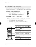
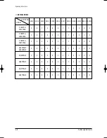
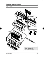
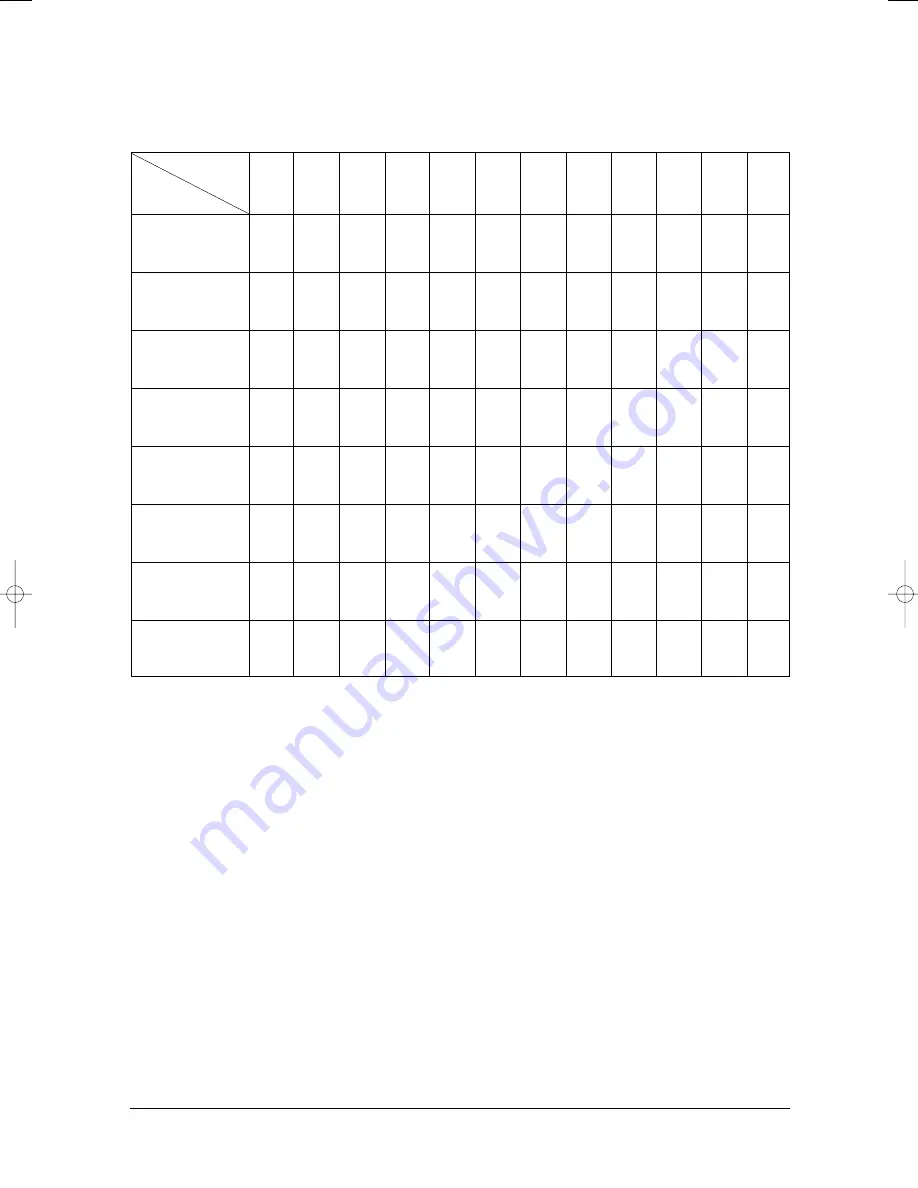
OPTION ITEMS
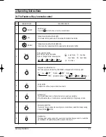
REMOCON
MODEL
SEG1
SEG2
SEG3
SEG4
SEG5
SEG6
SEG7
SEG8
SEG9 SEG10 SEG11 SEG12
SH12ZPG
SH12ZPGA
SH09ZPG
SH09ZPGA
SH07ZPG
SH07ZPGA
AQ12PGGE
AQ12PBGE
AQ09P8GE
AQ09PBGE
AQ07P8GE
AQ07PBGE
0
6
7
0
6
6
1
7
0
3
6
2
0
2
6
5
6
6
1
7
0
3
4
0
0
2
6
0
6
5
1
7
0
2
2
E
0
6
7
0
6
5
1
7
0
3
6
2
0
2
6
0
6
4
1
7
0
3
4
0
0
2
6
0
6
5
1
7
0
3
4
0
0
2
6
0
6
4
1
7
0
2
2
E
0
2
6
0
6
5
1
7
0
2
2
E
DB98_11830A(1)_1~56 4/17/03 4:54 PM Page 2-8
Summary of Contents for UQ07P8GE
Page 23: ...MEMO Samsung Electronics 3 10 ...
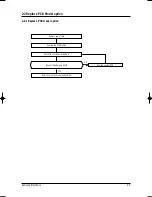
Page 37: ...Samsung Electronics 5 1 5 Block Diagrams 5 1 Refrigerating Cycle Block Diagram ...
Page 46: ...Samsung Electronics PCB Diagrams 6 9 BOTTOM ...
Page 49: ...Samsung Electronics 7 1 Code No DB98 08470A 7 Wiring Diagrams 7 1 Indoor Unit 7 1 1 12K BTU ...
Page 50: ...7 2 Samsung Electronics Wiring Diagrams Code No DB98 08708A 7 1 2 9K BTU 7K BTU ...
Page 52: ...8 1 Samsung Electronics 8 Schematic Diagrams 8 1 Indoor Unit 8 1 1 12K BTU AC PART ...
Page 53: ...Schematic Diagrams Samsung Electronics 8 2 8 1 2 12K BTU DC PART ...
Page 54: ...Schematic Diagrams 8 3 Samsung Electronics 8 1 3 9K BTU 7K BTU MAIN PART ...
Page 55: ...MEMO Samsung Electronics 8 4 ...
Page 56: ...MEMO 8 5 Samsung Electronics ...
Page 58: ...ELECTRONICS Samsung Electronics Co Ltd Apr 2003 Printed in Korea Code No DB98 11830A 1 ...


