


Disassembly and Reassembly
3-5
Samsung Electronics
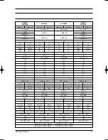
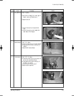
No
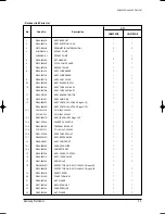
Parts
Procedure
Remark
2
3
4
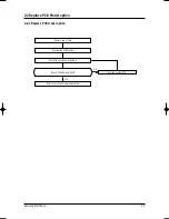
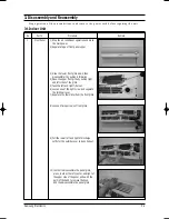
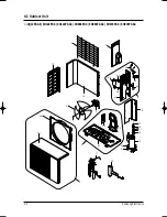
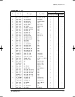
Fan and Motor
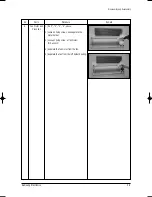
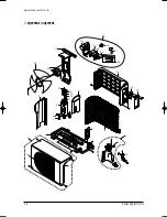
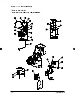
Heat Exchanger
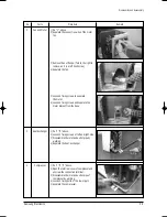
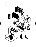
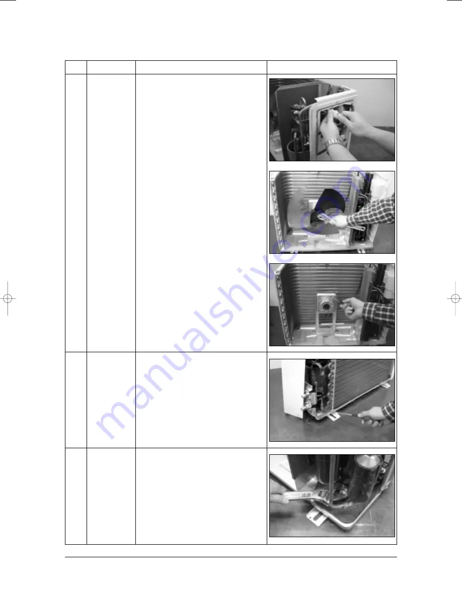
Compressor
1) Do “1”, above.
2) Separate the connection wire of the motor
fan.
3) Remove the nut flange. (Turn to the right to
remove, as it is a left hand screw)
4) Separate the fan.
5) Loosen 4 fixing screws to separate
the motor.
6) Loosen 4 fixing screws and separate the
motor bracket from the base.
1) Do "1","2", above.
2) Loosen 2 fixing screws of left and right side.
3) Disassemble the inlet and outlet pipe by
welding.
4) Separate the heat exchanger.
1) Do "1","2","3", above.
2) Open the terminal cover of compressor and
unscrew the connection terminal.
3) Disassemble the inlet and outlet pipe of
compressor by welding.
4) Loosen 3 fixing bolts of the lower part.
5) Separate the compressor.
DB98_11830A(1)_1~56 4/17/03 4:54 PM Page 3-5
Summary of Contents for UQ07P8GE
Page 23: ...MEMO Samsung Electronics 3 10 ...
Page 37: ...Samsung Electronics 5 1 5 Block Diagrams 5 1 Refrigerating Cycle Block Diagram ...
Page 46: ...Samsung Electronics PCB Diagrams 6 9 BOTTOM ...
Page 49: ...Samsung Electronics 7 1 Code No DB98 08470A 7 Wiring Diagrams 7 1 Indoor Unit 7 1 1 12K BTU ...
Page 50: ...7 2 Samsung Electronics Wiring Diagrams Code No DB98 08708A 7 1 2 9K BTU 7K BTU ...
Page 52: ...8 1 Samsung Electronics 8 Schematic Diagrams 8 1 Indoor Unit 8 1 1 12K BTU AC PART ...
Page 53: ...Schematic Diagrams Samsung Electronics 8 2 8 1 2 12K BTU DC PART ...
Page 54: ...Schematic Diagrams 8 3 Samsung Electronics 8 1 3 9K BTU 7K BTU MAIN PART ...
Page 55: ...MEMO Samsung Electronics 8 4 ...
Page 56: ...MEMO 8 5 Samsung Electronics ...
Page 58: ...ELECTRONICS Samsung Electronics Co Ltd Apr 2003 Printed in Korea Code No DB98 11830A 1 ...


