background image

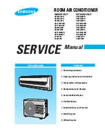
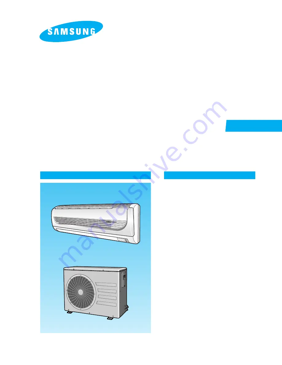
INDOOR UNIT

AS18WJWB
AS18WJWD
AS18WJWE
AST18WJWB
AST18WJWE
AS24W6WB
AS24W6WE
AST24W6WB
AST24W6WE
SC18ZWJ
SC24ZW6

OUTDOOR UNIT

US18WJWB
US18WJWD
US18WJWE
UST18WJWB
UST18WJWE
US24W6WB
US24W6WE
UST24W6WB
UST24W6WE
SC18ZWJX
SC24ZW6X

SERVICE

Manual

CONTENTS

AIR CONDITIONER

1. Product Specifications

2. Operating Instructions & Installation

3. Disassembly and Reassembly 

4. Refrigerating Cycle Diagram

5. Set Up the Model Option

6. Troubleshooting

7. Exploded Views and Parts List

8. Block Diagram

9. Wiring Diagram

ROOM AIR CONDITIONER

Summary of Contents for US18WJWB

Page 1: ...JWB UST18WJWE US24W6WB US24W6WE UST24W6WB UST24W6WE SC18ZWJX SC24ZW6X SERVICE Manual CONTENTS AIR CONDITIONER 1 Product Specifications 2 Operating Instructions Installation 3 Disassembly and Reassembly 4 Refrigerating Cycle Diagram 5 Set Up the Model Option 6 Troubleshooting 7 Exploded Views and Parts List 8 Block Diagram 9 Wiring Diagram ROOM AIR CONDITIONER ...

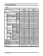
Page 2: ... Outdoor unit Indoor unit Outdoor unit 1 Product Specifications 1 1 Table Perfor mance Power Size Model Item AS18WJWB AST18WJWB AS24W6WB AST24W6WB Type Cooling kcal h 1 BTU h 2 Dehumidifying h Air Volume Cooling m3 min Noise Cooling dB Energy Efficiency BTU Wh 1 BTU Wh 2 Power ø V Hz Power Consumption kW Operating Current A Power Factor Cooling Starting Current A Length m Power Cord Number of Core...

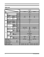
Page 3: ...m3 min Noise Cooling dB Energy Efficiency Cooling W W BTU Wh Power ø V Hz Power Consumption Cooling kW Operating Current Cooling A Power Factor Cooling Starting Current A Length m Power Cord Number of Core Wire Capacity A Outer Dimension Width x Height mm x Depth inch Weight kg Refrigerant Pipe Liquid mm x L m Gas mm x L m Drain Hose D x L mm Type Compressor Motor Type Rated Output Oil Type Type B...

Page 4: ...ndoor unit Outdoor unit Indoor unit Outdoor unit Table cont Perfor mance Power Size Model Item AS18WJWE AST18WJWE SC18ZWJ AS24W6WE AST24W6WE SC24ZW6 Type Cooling kW BTU h Dehumidifying h Air Volume Cooling m3 min Noise Cooling dB Energy Efficiency Cooling W W BTU Wh Power ø V Hz Power Consumption Cooling kW Operating Current Cooling A Power Factor Cooling Starting Current A Power Cord Length m Num...

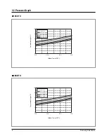
Page 5: ... C Low pressure kg cm G 10 8 6 4 2 0 25 0 35 0 45 0 55 0 Low Pressure Distribution Cooling mode Outdoor Temp DB C 18K BTU DB32 4 WB24 0 DB30 6 WB22 5 DB27 0 WB19 0 DB24 0 WB17 0 DB21 0 WB15 0 Indoor Temp C Low pressure kg cm G 10 8 6 4 2 0 25 0 35 0 45 0 55 0 Low Pressure Distribution Cooling mode Outdoor Temp DB C 24K BTU ...

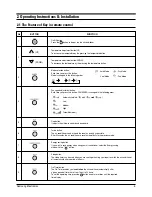
Page 6: ...button Mode is changed in the following order UP Flap button It adjusts the airflow to upward and downward Temperature adjustment button UP To increase the temperature by the pressing the temperature button Turbo button The air conditioner cools or heats the room as quickly as possible After 30minutes the air conditioner is reset automatically to the previous mode Auto Mode Dry Mode Cool Mode Fan ...

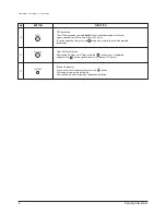
Page 7: ...ff Timer set Battery life indicator If you want to check the battery life press the button The longer will remain the battery life If one battery life indicator remains replace new batteries Off Timer button The Off Timer enables you to switch off the air conditioner automatically after a given period of time that is from 1 hour to 24 hours To set the operating time press the button one or more ti...

Page 8: ... automatical ly raised by 1 C each 1hour When the temperature has been raised by total of 2 C that temperature is maintained 6 FAN SPEED Fan speed automatically varies depending on both the difference between setting and the room tem perature Can set up the fan speed in COOL FAN mode 7 COMPULSORY OPERATION For operating the air conditioner without the remote control The operating is the same funct...

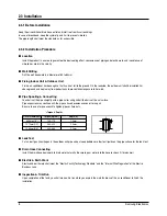
Page 9: ...ng Connecting You shall cut the pipe straightly with a pipe cutter and grind all the burrs of the cut surface Pipe expansion may continue until the pipe surface becomes uneven or torn apart Be sure to use a torque wrench to tighten pipes or flare nuts Leak Test Put an inert gas like nitrogen in the outdoor unit pipe and put soap bubbles or other test liquids on the pipe surface for the leak test D...

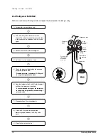
Page 10: ...old gauge clockwise Remove the hose of the low pressure side of manifold gauge 7 Check for gas leakage At this time especially check for gas leakage from the 3 Way valve s stem nuts and from the service port cap 2 Connect the charging hose of low pressure side of manifold gauge to the packed valve having a service port 3 8 Packed valve as shown at the figure 5 Set valve cork of both liquid side an...

Page 11: ...it to cool operation mode 7 Stop operation of the air conditioner 9 Close the cap of each valve 2 Turn the 3 Way valve clockwise to close connect the pressure gauge low pressure side to the service valve and open the 3 Way valve again 5 Check the pressure indicated by the pressure gauge low pressure side Standard pressure is should be 4 5 5 5kg cm2 in a regular high operation mode 6 Open the refri...

Page 12: ...ion of the air conditioner Relocation of the air conditioner Refer to this procedure when the unit is relocated Carry out the pump down procedure refer to the details of pump down Remove the power cord Disconnect the assembly cable from the indoor and outdoor units Remove the flare nut connecting the indoor unit and the pipe At this time cover the pipe of the indoor unit and the other pipe using a...

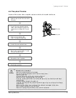
Page 13: ... repairing the unit No Parts Procedure Remark 1 Front Grille 1 Stop the air conditioner operation and shut off the main power 2 Open the Front Grille by pulling right and left sides of the hook 3 Loosen 1 of the right screw and detach the Terminal Cover 4 Detach the thermistor from the Front Grille 5 Loosen 3 fixing screws of Front Grille ...

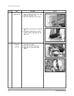
Page 14: ...lock 3 hooks to fix Panel Front and Tray Drain 7 Unlock 3 hooks to fix Panel Front and Back Body 1 Take all the connector of PCB upper side out Inclusion Power Cord 2 Detach the outdoor unit connection wire from the Terminal Block 3 Loosen 4 fixing screws of Ass y Control In 1 Pull Tray Drain out from the Back Body ...

Page 15: ...ws of right side 2 Detach the Connection Pipe 3 Detach the Holder Pipe at the rear side 4 Loosen the 4 fixing screws of right and left side 5 Lifting the Heat Exchanger up a little to push the up side for separation from the indoor unit 1 Loosen the fixing screw 2 Detach the Fan Motor from the Fan 3 Detach the Fan From the left Holder Bearing ...

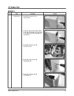
Page 16: ...Cover Control 2 Loosen the fixing screws on right and left back Cabinet Side edge and a fixing screw on the Cabinet Front lower to detach the Cabinet Front 3 Loosen the fixing screws of the Ass y Control Out 4 Loosen the fixing screws of the Cabinet Side RH 5 Loosen the fixing screws of the Cabinet Side LF 18K BTU ...

Page 17: ...rews to detach the Motor 1 Loosen 3 fixing screws of the Bar Steel 2 Loosen 2 fixing screws on both sides 3 Disassemble the pipe in both inlet and outlet with welding torch 4 Detach the Heat Exchanger 1 Loosen the Terminal Cover nut to open the Terminal Cover 2 Disassemble the cloth sound felt 3 Disassemble the pipe in both inlet and outlet of the Compressor with welding torch 4 Loosen the 3 bolts...

Page 18: ...mark 1 Common Work 1 Loosen the fixing screw of the Cover Control 2 Loosen the fixing screws of the Cabinet Upper 3 Loosen the fixing screws of the Cabinet Side RH 4 Loosen the fixing screws of the Cabinet Side LF 5 Loosen the fixing screws of the Ass y Control Out 24K BTU ...

Page 19: ...ixing screws to detach the Motor 1 Loosen 2 fixing screws on both side 2 Disassemble the pipe in both inlet and outlet with welding torch 3 Detach the Heat Exchanger 1 Loosen the Terminal Cover to open the Terminal Cover 2 Disassemble the Cloth Sound Felt 3 Disassemble the pipe in both inlet and outlet of the Compressor with welding torch 4 Loosen 3 bolts at the bottom 5 Detach the Compressor ...

Page 20: ...rigerating Cycle Diagram Indoor Unit Outdoor Unit Heat Exchanger Evaporator Gas side 3 Way valve 2 Way valve Liquid side Capillary tube Cooling Gas leak check point Cross fan Heat Exchanger Condenser Propeller fan Compressor T1 T2 ...

Page 21: ...ariation 25 0 C 55 0 C Cooling Capacity Btu h 30 000 20 000 10 000 25 0 35 0 45 0 55 0 Cooling Capacity Distribution Outdoor Temp DB C DB32 4 WB24 0 DB30 6 WB22 5 DB27 0 WB19 0 DB24 0 WB17 0 DB21 0 WB15 0 Indoor Temp C 18K BTU Cooling Capacity Btu h 30 000 20 000 10 000 25 0 35 0 45 0 55 0 Cooling Capacity Distribution Outdoor Temp DB C DB32 4 WB24 0 DB30 6 WB22 5 DB27 0 WB19 0 DB24 0 WB17 0 DB21 ...

Page 22: ...r consumption W 4 000 3 500 3 000 2 500 2 000 1 500 1 000 25 0 35 0 45 0 55 0 Power consumption Distribution Cooling mode Outdoor Temp DB C DB32 4 WB24 0 DB30 6 WB22 5 DB27 0 WB19 0 DB24 0 WB17 0 DB21 0 WB15 0 Indoor Temp C Power consumption W 4 000 3 500 3 000 2 500 2 000 1 500 1 000 25 0 35 0 45 0 55 0 Power consumption Distribution Cooling mode Outdoor Temp DB C DB32 4 WB24 0 DB30 6 WB22 5 DB27...

Page 23: ...re 3 1 4 2 5 Setting Option SEG1 Push the button to set the display panel to Every time you push the button the display panel reads repeatedly 2 Setting Option SEG2 Push the button to set the display panel to Every time you push the button the display panel reads repeatedly 4 Setting Option SEG3 Push the button to set the display panel to Every time you push the button the display panel reads repe...

Page 24: ...isplay panel to Every time you push the button the display panel reads repeatedly 9 Change it into the set display of Option SEG7 and SEG8 with the button 11 Setting Option SEG8 Push the button to set the display panel to Every time you push the button the display panel reads repeatedly 13 Setting Option SEG9 Push the button to set the display panel to Every time you push the button the display pa...

Page 25: ... the input of option is completed If the ding sound isn t heard try again pressing the ON OFF button Step 5 Unit operation test run First Remove the battery from the remote control Second Re insert the battery into the remote control Third Press ON OFF key with the direction of remote control for set Error Mode 1st If all lamps of indoor unit are flickering Plug out plug in power plug again and pr...

Page 26: ...option Code AS18WJWB AS18WJWE AST18WJWB AST18WJWE SC18ZWJ AS24W6WB AS24W6WE AST24W6WB AST24W6WE SC24ZW6 Model Option Code SEG1 SEG2 SEG3 SEG4 SEG5 SEG6 SEG7 SEG8 SEG9 SEG10 6 0 0 0 0 5 0 2 2 E AS18WJWD 6 0 0 0 0 A 0 3 5 1 6 0 0 0 0 5 0 3 4 0 ...

Page 27: ...ir conditioner does not operate The compressor and indoor fan stop intermittently in HEAT mode Indoor fan and outdoor fan stop operation intermittently in a HEAT mode The compressor stops intermittently in a COOL mode or DRY mode and fan speed of the indoor unit decreases 1 2 3 4 5 6 7 8 9 Operation of air conditioner Explanation It indicates power is on The LED stops blinking if the opera tion ON...

Page 28: ...MP OPERATION TIMER TURBO No response from the remote control operation signal Unable to operate the outdoor unit Plug out and plug in 5 seconds later Press the TURBO button with the remote control In 3 minutes check the voltage between the indoor unit terminal block N1 and 1 Able to operate the remote control Unable to operate the remote control AC200V AC240V No power source displayed OK Press the...

Page 29: ...nplug the power cord and plug it after 5 seconds Check the setting temperature operate Check the display board Check the indoor unit control board No Reconnect wires correctly Check whether two wires of power cord are connected correctly to the terminal block and control board Press the Power Button on the remote control unit to operate the air conditioner No Replace fuse Check whether the fuse on...

Page 30: ...B board 2 Troubleshooting procedure Yes Yes Yes Yes After unplugging out the power cord should be reconnected within 5 seconds No Check as in the procedure No power parts No Micom should be replaced Does the Solid State Relay SS71 work properly Does the OPERATION lamp blink Micom is out of order Test rod location PCB CN72 Condition pin 3 and 5 Fan operate About AC 180V Normal Voltage No PCB should...

Page 31: ...MINAL BLOCK connector N1 L1 1 2 3 4 2 Troubleshooting procedure Yes Yes No Yes Yes Yes No After unplugging out the power cord should be reconnected within 5 seconds Does the timer lamp blink during operation No Check as in the procedure No Power parts No PCB should be checked Is the power relay RY71 operated by adjusting the room temperature Does the OPERATION lamp blink Micom is out of order PCB ...

Page 32: ... procedure Yes No Yes Yes Remove power cord and plug in again in approx 5 seconds UP DOWN louver motor is faulty No Check as in the procedure No Power parts Yes Normal Does operation start when swing button of the remote control unit pushed Does the OPERATION lamp blink No Micom IC04 is faulty Voltage at pin 57 60 of micom IC04 change Squarewave No Driver IC06 08 ULN2003A is faulty Voltage at pin ...

Page 33: ...1 connector No Yes Yes Yes After training on the heating operation should start in 5 minutes 4 Way valve should be replaced or connecting Cable Check No No Abnormal Micom Is the number checking 13 of IC05 ULN2003A LOW Is the number 38 of Micom IC04 DC5 0V No Abnormal IC05 Is the voltage between CN71 1 and CN71 5 rating voltage 10 range No Abnormal RY73 PCB should be replaced Abnormal 4 Way valve o...

Page 34: ...om the ASS Y PCB CN43 connector and measure the sensor resistance with an ohmmeter tester Connect the sensor to CN43 supply power and measure the voltage of 1 and 2 of the CN43 connector MICOM Error or Connector CN43 check Is the sensor resistance value 10KΩ 3 at the room temperature of 25 C Yes Poor ASS Y PCB Replace Below 0 5V Yes Poor ASS Y PCB Replace Over 4 9V Indoor unit room temperature sen...

Page 35: ...3 8 When the remote control is not receiving 1 Check if the connector was normally assembled 2 Put the set in operation and check the voltage of No 3 and No 2 of the main PCB CN91 while operating the remote control When the voltage descends below 3V the assembly module PCB is normal and the main PCB is poor Then replace the main PCB 3 Replace the assembly display PCB because the module PCB is poor...

Page 36: ...FAN Speed High 2 Continuous Operation 1 Is the fuse disconnected F701 Checking the power voltage 1 Is the DB71input voltage AC200V AC240V 2 Is the voltage between both terminals of the C102 on the 2nd side of the transformer AC12V 0 5V 3 Is the voltage between both terminals of OUT and GND of IC02 KA78L05 DC5V 0 5V Checking the power voltage 1 Check the voltage of the relay RY71 coil IC05 PIN 11 a...

Page 37: ...15 14 13 12 11 10 9 8 7 6 5 4 3 2 1 0 1 2 3 4 5 6 7 8 9 4 300 4 444 4 594 4 749 4 912 5 080 5 256 5 439 5 630 5 828 6 033 6 246 6 468 6 699 6 941 7 192 7 455 7 729 8 015 8 313 8 622 8 944 9 281 9 632 10 10 380 10 780 11 200 11 630 12 090 12 560 13 060 13 570 14 120 14 680 15 280 15 900 16 550 17 240 17 960 18 700 19 480 20 290 21 150 22 050 22 990 23 900 25 030 26 130 27 280 28 470 29 720 31 040 3...

Page 38: ... the normal temperature 10 C 30 C Abnormal 0Ω Open or Short Measure the resistance between motor wires with a tester Normal At the normal temperature 10 C 30 C Abnormal 0Ω Open or Short Measure the resistance between the red wire and each terminal wire with a tester Normal About 300Ω at the normal temperature 20 C 30 C Abnormal 0Ω Open or Short Breakdown Inspection Method Part Compare terminal Res...

Page 39: ... 2 3 2 2 3 7 17 10 4 9 7 2 1 2 5 1 5 4 5 2 5 3 8 5 3 3 4 3 6 3 8 3 1 3 2 3 5 3 3 11 13 15 12 You can search for the updated part code number through the ITSELF URL http itself sec samsung co kr 7 Exploded Views and Parts List 7 1 Indoor Unit ...

Page 40: ...ASS Y CONTROL IN ASS Y 1 1 1 DB93 02830B ASS Y CONTROL IN ASS Y 1 5 DB92 00632E ASS Y PANEL FRONT ASS Y 1 DB92 00632F ASS Y PANEL FRONT ASS Y 1 1 DB92 00632C ASS Y PANEL FRONT ASS Y 1 5 1 DB64 01184B PANEL FRONT ABS 1 1 1 1 5 2 DB64 01182B GRILLE INLET ABS 1 1 1 1 5 3 DB93 02867B ASSY DISPLAY ASS Y 1 1 1 1 5 4 DB63 01186A GUARD AIR FILTER PP 1 DB63 01186C GUARD AIR FILTER PP 1 1 1 6 DB70 00505A PL...

Page 41: ... HOSE ASS Y 1 1 1 4 DB93 02830D ASS Y CONTROL IN ASS Y 1 1 1 5 DB92 00632E ASS Y PANEL FRONT ASS Y 1 DB92 00632F ASS Y PANEL FRONT ASS Y 1 DB92 00632C ASS Y PANEL FRONT ASS Y 1 5 1 DB64 01184B PANEL FRONT ABS 1 1 1 5 2 DB64 01182B GRILLE INLET ABS 1 1 1 5 3 DB93 02867B ASSY DISPLAY ASS Y 1 1 1 5 4 DB63 01186A GUARD AIR FILTER PP 1 DB63 01186C GUARD AIR FILTER PP 1 1 6 DB70 00505A PLATE HANGER SGCC...

Page 42: ...MEMO 41 Samsung Electronics ...

Page 43: ...Samsung Electronics 42 7 2 Outdoor Unit 3 1 3 2 16 21 10 5 8 18 11 12 13 6 3 1 7 15 17 4 9 2 19 20 14 14 2 14 3 14 1 18K BTU ...

Page 44: ...E MOTOR FAN YDK95 45 4 1 1 DB31 00265F MOTOR FAN YDK95 45 6 1 1 1 12 DB67 00238A FAN PROPELLER AS GF20 1 1 1 13 DB60 30020A NUT FLANGE M6 1 1 1 14 DB93 02966A ASS Y CONTROL OUT ASS Y 1 DB93 02966B ASS Y CONTROL OUT ASS Y 1 DB93 02967B ASS Y CONTROL OUT ASS Y 1 14 1 2301 001370 C FILM 2 5uF 450VAC 1 1 1 14 2 2501 001240 C OIL 50uF 450VAC 1 2501 001239 C OIL 45uF 450VAC 1 1 14 3 DB65 00167A TERMINAL...

Page 45: ...R SGCC M 1 1 10 DB97 02225B ASS Y SUPPORT PLATE B M ASS Y 1 1 11 DB31 00265E MOTOR FAN YDK95 45 4 1 1 1 12 DB67 00238A FAN PROPELLER AS GF20 1 1 13 DB60 30020A NUT FLANGE M6 1 1 14 DB93 02966A ASS Y CONTROL OUT ASS Y 1 DB93 02967A ASS Y CONTROL OUT ASS Y 1 14 1 2301 001370 C FILM 2 5uF 450VAC 1 1 14 2 2501 001240 C OIL 50uF 450VAC 1 1 14 3 DB65 00167A TERMINAL BLOCK 2P 1 DB65 00164C TERMINAL BLOCK...

Page 46: ...MEMO 45 Samsung Electronics ...

Page 47: ...Samsung Electronics 46 Exploded Views and Parts List 3 2 1 11 7 17 8 16 1 16 2 16 3 16 16 4 18 19 10 9 4 5 6 15 14 12 13 24K BTU ...

Page 48: ... ASS Y CABI UP ASS Y 1 1 12 55B260JT1EM SS ROTARY COMPRESSOR ROTARY 1 55A260IT1EM SS ROTARY COMPRESSOR ROTARY 1 13 DB96 04351A ASS Y TUBE SUCTION ASS Y 1 1 14 DB96 04352A ASS Y TUBE DISCHARGE ASS Y 1 DB96 04352B ASS Y TUBE DISCHARGE ASS Y 1 15 DB96 04357A ASS Y TUBE CAPILLARY ASS Y 1 DB96 04357C ASS Y TUBE CAPILLARY ASS Y 1 16 DB93 03238A ASS Y CONTROL OUT ASS Y 1 DB93 03238D ASS Y CONTROL OUT ASS...

Page 49: ...88B DB93 02788D DB93 02793A DB70 00507A DB61 01980A 6001 000929 6001 001054 DB39 00147A DB32 00020D DB63 00851A DB73 00242B 24K BTU AST18WJW AS18WJW SC18ZWJ 24K BTU 18K BTU S N S N Specification 7 3 Ass y Control In N1 NATURAL L1 LIVE 1 COMPRESSOR 2 FAN HIGH 3 FAN LOW CASE CONTROL IN ASS Y TERMINAL BLOCK ASS Y TERMINAL BLOCK ASS Y TERMINAL BLOCK ASS Y MAIN PCB ASS Y MAIN PCB ASS Y S W DISPLAY PCB ...

Page 50: ... SELECT H M L FLAP ON OFF TIMER SELECT ENERGY SAVING BATTERY CHECK TEMPERATURE SELECT ZERO VOLTAGE DETECT BLADE CONTROL INDOOR FAN MOTOR CONTROL COMPRESSOR CONTROL TEMPERATURE CONTROL TIMER BUZZER CONTROL OUTDOOR FAN MOTOR CONTROL 4 WAY VALVE CONTROL TRIGGER SIGNAL SSR COMPRESSOR DRIVE OUTDOOR FAN MOTOR DRIVE STEPPING MOTOR DRIVE BUZZER DRIVE 4 WAY VALVE DRIVE COMPRESSOR CONTROL SIGNAL STEPPING MO...

Page 51: ...Samsung Electronics 50 9 Wiring Diagram 9 1 Indoor Unit This Document can not be used without Samsung s authorization Code No DB98 20816A AST18WJWB AST18WJWE ...

Page 52: ...51 Samsung Electronics This Document can not be used without Samsung s authorization Indoor Unit cont Code No DB98 20815A AS18WJW SC18ZWJ ...

Page 53: ...Wiring Diagram Samsung Electronics 52 This Document can not be used without Samsung s authorization Code No DB98 20813A 24K BTU ...

Page 54: ...Electronics This Document can not be used without Samsung s authorization 9 2 Outdoor Unit MARK NAME FM FAN MOTOR US18WJW SC18ZWJX Code No DB98 21316A MARK NAME FM FAN MOTOR UST18WJWB UST18WJWE Code No DB98 20936A ...

Page 55: ...Samsung Electronics 54 This Document can not be used without Samsung s authorization MARK NAME FM FAN MOTOR 24K BTU Code No DB98 20929A Wiring Diagram ...

Page 56: ...MEMO 55 Samsung Electronics ...

Page 57: ...MEMO Samsung Electronics 56 ...

Page 58: ...e Manual is a property of Samsung Electronics Co Ltd Any unauthorized use of Manual can be punished under applicable International and or domestic law Samsung Electronics Co Ltd Jan 2005 Printed in Korea Code No DB98 21180A 1 ...

Reviews: