background image

6

/

66

cabinet from falling.

After the screen installation and connection is completed, do not step on the plug,

socket, power/signal cable.

Please use the accessories/accessories specified by our company.

2.3 Warning Statement

Do not open the internal equipment of the cabinet to reduce the risk of electric
shock. If modules has dead lamps, or the parts of the cabinet are damaged,
professional maintenance personnel should be required for maintenance.

If the power cord in the cabinet is damaged, do not try to repair the power cord.
Please replace the power cord with professional maintenance personnel.

Moisture-proof: The maximum relative humidity of the work should be less than
90% .

Dustproof: Do not place the display in a dusty environment and clean the surface
of the display regularly.

Dehumidification: Do not adjust the screen directly to the maximum brightness,
but gradually increase it.

Temperature and humidity range:

Working temperature and humidity range -30 ~ 50

/ 10% ~ 90%

Storage temperature and humidity range -30 ~ 60

/ 10% ~ 95%

Each main power cable can carry a maximum current of 16A. Note that the total

current of the cabinets cascaded in one main power cable should not exceed
16A. Refer to Table 7-1 for the specific quantity.

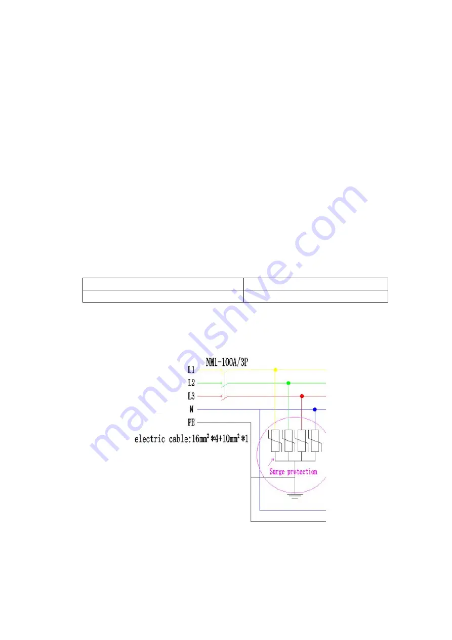
Surge protection device of power should be added in the power distributor

.

After the display is idle for a period of time, please turn on the power and input the

signal for the first time, and adjust the brightness of the display to the lowest level
for about half an hour and gradually increase the brightness gradually, then use it
normally.

Summary of Contents for VMR-O P3.9

Page 1: ...1 66 Product Manual VMR O P3 9 ...

Page 2: ...inet 14 5 4 Controller System 15 5 5 Other Accessories 17 Chapter 6 VMR O Installation Process 18 6 1 Place Installation 18 6 2 Hanging 23 Chapter 7 VMR O Cable Connection 26 7 1 VMR O HD series product cabinet interface introduction 26 7 2 Power Cable Connection 27 7 3 Signal cable connection 28 Chapter 8 VMR O Displaying Set up Steps 30 8 1 NovaLct Mars Control System Instruction 30 Appendix A D...

Page 3: ...enance High refresh rate high gray level high contrast and seamless matching enable VMR O series to deliver excellent image quality Super Slim Lightweight Design VMR O series has a panel depth of only 86 mm and less than 8 kg panel making it the lightest in its class and ideal for hanging applications Simple Precise Installation Support Snap Locking system with Magnetism Locating System help one p...

Page 4: ...when installing the display and precautions to prevent damage to the display Before installing the VMR O Series please ensure that you understand and follow the safety guidelines safety instructions and warnings in this section In this manual the VMR O HD Series contains the following products from the company for Outdoor Use VMR O P3 9 ...

Page 5: ...oken parts such as power lines data lines Sending boxes etc Parts for other manufacturer s products are not allowed to be used on the VMR O HD series Please follow the assembly instructions when installing the cabinet If you encounter any problems during the installation please contact Samsung in time Product Care The cabinet should be kept dry and clean It is recommended that users conduct safety...

Page 6: ...tproof Do not place the display in a dusty environment and clean the surface of the display regularly Dehumidification Do not adjust the screen directly to the maximum brightness but gradually increase it Temperature and humidity range Working temperature and humidity range 30 50 10 90 Storage temperature and humidity range 30 60 10 95 Each main power cable can carry a maximum current of 16A Note ...

Page 7: ...O HD series must meet the requirements When the VMR O HD series products are not used for a long time please cut off the power supply to avoid a safety accident When installing or disassembling the VMR O HD series products pay attention to the corners of the cabinet do not be impacted remove or install the protective angle of the cabinet in time and place the anti static carpet on the ground of th...

Page 8: ...th supporting floor stacking brackets to quickly install the display anytime anywhere The floor stand is set in units and multiple sets can be quickly combined to form a large stacking frame 3 2 Electrical Requirement Power supply working voltage is 100 240VAC 50 60Hz main power cable size is 3 2 5mm maximum safety current of cabinet power connector is 16A and the number of cabinets one main power...

Page 9: ...s of display screen 4 1 Displaying System Connection Diagram 1 Sending box send video data to the display 2 USB serial cable Communicate with computer set the sending box parameters through software 3 DVI line transmit the original video data to the sending box 4 Computer based on the windows system computer set the Sending box parameters play the program 5 Power cord power supply to the display 6...

Page 10: ...g Parts on the cabinet and the cabinet As shown in Picture 5 1 the VMR O HD series cabinet consists of four modules The cabinet size is 500 500mm and the size of each module is 250 250mm designed with magnetic structure can be quickly disassembled and assembled for front maintenance Picture 5 1 Cabinet Description of the accessories on the cabinet 1 Power cabinet cover contain other components oth...

Page 11: ... or curve connection 12 Automatic locking piece With the locking lever quick connection and locking the adjacent cabinet Remark The module housing in the Picture is applicable to VMR O P3 9 Main power cable Power supply to the display the wire diameter is 3 2 5mm and the maximum load current is 16A as shown in Picture 5 2 In the Picture 1 is the aviation head connected to the cabinet and 2 is the ...

Page 12: ...between the cabinet and the cabinet The cable size is 3 2 5mm as shown in Picture 5 4 Picture 5 4 Cabinet Power Line Cabinet signal cable Connects the signal between the cabinet and the cabinet and exceeds the five types of network cables as shown in Picture 5 5 Picture 5 5 Signal cable ...

Page 13: ... shown in Picture 5 6 Picture 5 6 Hanging Bar 1 For holding the truss 2 For Locking the locking bars of the two adjacent cabinets 5 2 2 Floor stacking bracket The stacking bracket can be freely combined into a larger frame to meet the installation requirements as shown in Picture 5 7 ...

Page 14: ...Bracket Stacking base beam and standing base bar Maintenance channel board Connector Support Truss Frame 5 3 Power Distribution Cabinet Powering the entire display system As Picture 5 9 show Picture 5 9 Power Distribution Cabinet ...

Page 15: ...rfaces 5 4 Controller System Sending box Receives and processes the DVI video signal and sends the video data to the receiving card through the network cable The front and back of the sending box are shown in Picture 5 10 Picture 5 10 Front Rear View Receiving card Receive and process the data transmitted by the sending box so that the video is perfectly displayed on the display The receiving card...

Page 16: ...isplay brightness adjustment and other functions The software interface is shown in Picture 5 12 Picture 5 12 NovaLCT Mars Control System Interface Video processor processing various video signals converting DVI HDMI AV VGA and other signals into DVI signals improving picture quality providing a better picture for the display as ...

Page 17: ...video source for the display The physical object is shown in Picture 5 14 Different items will choose different types of video players the appearance and function will be different Picture 5 14 HD Media Displayer 5 5 Other Accessories Vacuum tool When using the module take the module and remove the module from the cabinet to achieve pre maintenance For details see Appendix D How to use the air suc...

Page 18: ... VMR O HD series products and guides the customer to install the products correctly The VMR O HD series products generally adopt two installation methods stacking and hangig which are described in detail in this chapter 6 1 Place Installation In the case of frequent replacement of the screen use location the installation method of the seat is usually adopted The company provides customers with a n...

Page 19: ... cabinets accessories tools and other materials are ready in place 6 1 2 Folding bracket installation instruction Step 1 Install the base beam The base beam is the first layer of a screen to ensure flatness The base beam can be spliced into the length as requeste by installation requirements as shown in Picture 6 1 Picture 6 1 Stacking Base Beam Step 2 Install the standing base bar Align the base ...

Page 20: ...he maintenance access board on the bracket as shown below which is convenient for maintenance as shown in Picture 6 4 Picture 6 4 Maintenance Access Board Step 5 Install the bracket connector The height of the connector is determined by the height of the cabinet as shown in Picture 6 5 ...

Page 21: ...ly and gentle way and unwrap the PE package and press the automatic protection angle If the cabinet is not equipped with the automatic corner guard the sheet metal corner can be removed with a screwdriver And place the cabinet completely on the ground or on the desktop as shown in Picture 6 6 6 7 Picture 6 6 Take out cabinet Picture 6 7 Press to unfold the automatic connection corner ...

Page 22: ... connecting piece and connect the cabinet to the stacking bracket via bracket connector as shown in Fig 6 8 1 2 2 shown Plug in the power cable and signal cable into socket of the cabinet a crispy sound after plugging indicates good connection Picture 6 8 1 Rotate the left and right lock levers of the lock cabinet in the direction of the cabinet mark Picture 6 8 2 Bracket Connector 4 Repeat Step 3...

Page 23: ... For the VMR O HD Series Samsung provides customers with a truss and FlyKit for quick haing installation The following are detailed steps 6 2 1 Preparatory Work 1 Select the installation area of the VMR O HD display and enclose it with a safety warning band Non workers should not enter without permission keep the installation area clean free from dirt and debris 2 Ensure that you have read underst...

Page 24: ...n in Picture 6 12 Picture 6 12 Hanging Bra Installation 3 Cabinet Installation Picture 6 13 Cabinet Installation 1 First wear anti static gloves and operate with more than one person 2 The single unit of the cabinet is carefully taken out from the flightcase and the PE tape and the protection angle are removed in turn If the cabinet is not equipped with ...

Page 25: ...dead lights and obvious bright lines Plug in the power cable and signal cable into socket of the cabinet a crispy sound after plugging indicates good connection Picture 6 16 Lock the cabinets 4 Repeat step 3 Until the entire screen is installed Refer to Chapters 7 and 8 for the steps to debug the display 6 2 3 Precautions 1 During the installation process pay attention to the protection of the cab...

Page 26: ...Output Input Note The Seetronic head is used for the 1 4 interface All electrical parameters refer to its specifications power interfaces are strictly differentiated between input and output When cascaded the output interface of the cabinet is connected to the next cabinet input signal interface is the RJ45 interface These two interfaces are independent of input and output After the signal is conn...

Page 27: ...main power supply must be 20 0 8 16A VMR O HD series display operating voltage range is 100 240V AC outdoor single cabinet power consumption is about 240W under different input voltage conditions The number of cabinets on a main power cord is different For the specific number please refer to Table 7 1 100 240VAC the outdoor single cabinet power consumption is about 240W Under different input volta...

Page 28: ...When the transmission distance is greater than 70m it is possible to transmit data by optical fiber and the longest distance is 20 kilometers Cabinet signal cable used for signal transmission between cabinets 7 3 3 Display Signal cable connection 1 Install the sending box arrange the main signal and put it next to the display installation position 2 Install the cabinet refer to Chapter 6 3 After t...

Page 29: ... Signal connection diagram Product Name Daisy Chain Cabinet Qty for 1 main signal cable to cascade VMR O P3 9 575 000pixels 35PCS 39PCS 650 000pixels Remarks The number of pixels carried on each main network cable of the sending box is limited and the actual project should refer to the corresponding signal connection diagram ...

Page 30: ... profile Double click to open the NovaLCT Mars software as shown in Picture 8 10 click User Advanced Login to open the software setting interface as shown in Picture 8 10 Picture 8 10 A password window pops up as shown in Picture 8 11 Enter the password 666 to pop up the parameter setting window as shown in Picture 8 11 Click the Confirm button on the Screen Config interface as shown in Picture 8 ...

Page 31: ...d files button on the Scan Board interface load the rcfgx file corresponding to the display and then click the Send to HW button After the display shows normal click Save as shown in Picture 8 12 Picture 8 13 Picture 8 12 Picture 8 13 ...

Page 32: ...ed and sent to the receiving card After sending and saving the configuration file the display should display the same content in units of the cabinet To load the screen file 8 1 2 Screen connection file loading Click Read file in the Screen connection interface of the software parameter settings Button load the scr file then click the Send to HW button After the display shows normal click Save as ...

Page 33: ...le needs to be reloaded and sent to the receiver card At this point the entire screen connection parameter setting has been completed At this time the entire screen should be displayed on the desktop of the computer Next you can play the program you want in the initial interface of NovaLCT Mars For details please refer to the software manual It can be seen in the Help submenu under the software in...

Page 34: ...34 66 Appendix A Dimensional Drawing of Main Components A 1 VMR O VMR O P3 9 Flat Panel Curve Panel A 2 Flykit ...

Page 35: ...cal Pixel Density m2 65 536 pixels m2 Pixel Density Panel 16 384 pixels panel LED Module Dimensions mm 250 250 Panel Dimensions W H D mm 500 500 86 No of Modules Per Panel W H 2 2 Physical Resolution of Module W H 64 64 Physical Resolution of Panel W H 128 128 Weight Per Panel 7 9 0 3 kg panel Weight Per m 31 6 1 2kg m Cabinet Material Aluminum Die casting Max Stacking 20 panels Max Hanging 16 pan...

Page 36: ...st Ratio 4 000 1 Electrical Environmental Average Power Consumption 288 w sqm Max Power Consumption 960 w sqm Max Daisy Chain Signal 35 575 000pixels 39 cabinets 650 000pixels Power 14 cabinets 220v 7 cabinets 110v Operating Temp Humidity 30 50 C 10 90 Storage Temp Humidity 30 60 C 10 95 Expected LED Lifetime Max 100 000 Hrs Certification Certification CE EAC ETL FCC KCC UL CB CCC Power Max Power ...

Page 37: ... 9 204030000050B HUB board outdoor 3 9 5 Connection plate outdoor 3 9 204050000097B connecting plate outdoor 3 9 6 Power cord 0 35M SEETRONIC outdoor 208030200204R Power Cord 0 35M SEETRONIC Outdoor 7 Up and down signal cable 0 4M SEETRONIC outdoor 209020200041R up and down signal cable 0 4M SEETRONIC outdoor 8 Left and right signal cable 0 75M SEETRONIC outdoor 209020200040R Left and right signal...

Page 38: ...IC outdoor 209010200054R Main signal cable 30M SEETRONIC outdoor 11 Mask Outdoor 3 9 120200207146R Mask Outdoor 3 9 12 Light Nationstar 1921 110000290001R Lights National Star 1921 13 IC ICND2038S 110900203801R IC ICND2038S 14 Protection rope 120700404014R protection rope buckle 15 Mask screw PA1 2 4 120300604021R Mask Screw PA1 2 4 16 IC 74HC245PW 110902H24521R IC 74HC245PW ...

Page 39: ...mother power aviation head 120500207012R SEETRONIC outdoor female power aviation head 19 SEETRONIC outdoor public power aviation head 120500207013R SEETRONIC outdoor male power aviation head 20 SEETRONIC outdoor signal aviation head 120500407026R SEETRONIC outdoor signal aviation head 22 Sender Box Hexagonal Wrench MCTRL660 Standard ...

Page 40: ...ndix C Tools to be prepared C 1 Adjustable Wrench conventional C 2 Screwdriver medium size C 3 Cutting pliers conventional C 4 Allen key M3 is used to open the power cabinet M8 is used to fix the connecting piece ...

Page 41: ...41 66 C 5 Plastic hammer ...

Page 42: ...of the module to be removed and press it slightly on the surface of the module so that the suction cup of the suction tool fits evenly with the module surface as shown in the following Picture D 2 Press and hold the air suction tool switch for 3 5 seconds and the air suction tool sucks the module ...

Page 43: ...wn below D 4 After removing the module release the air suction tool switch and the module is successfully removed as shown below Remarks The VMR O HD series is a small pitch product that is very easy to damage All the actions need to be handled gently during the process of disassembling the module ...

Page 44: ...44 66 Appendix E How to use the upper and lower lock levers E 1 1 Stack one panel onto the other E 1 2 Push the lock lever up as shown below ...

Page 45: ... up into position and the lock bar lock lever is as shown below E 1 4 Move the handle to the inside according to the arrow of the cabinet so that the handle is pressed against the cabinet as shown below E 1 5 Locking status as shown below ...

Page 46: ... handle according to the UNLOCK direction of the cabinet to the point where it cannot be rotated Then push the lock piece pointed by the arrow to unlock it as shown below E 2 1 Initial state When the cabinet is installed the position of the upper right lock lever is as shown below ...

Page 47: ...k lever up as shown below E 2 3 The lock lever is pushed up into position and the lock bar lock lever is as shown below E 2 4 Move the handle to the inside of the cabinet arrow to press the handle to the cabinet as shown below ...

Page 48: ... E 2 6 Locate the left and right locks and unlock them Turn the lock lever handle according to the UNLOCK direction of the cabinet to the point where it cannot be rotated Then push the lock piece pointed by the arrow to unlock it as shown below ...

Page 49: ...49 66 ...

Page 50: ...itial state of the angle lock is as shown in the Picture below Adjust the position as shown in the Picture below to the desired angle F2 After the angle lock is adjusted to the required scale press the handle to press the handle and lock the angle to the desired angle as shown below ...

Page 51: ...51 66 F3 Align the left and right cabinets together as shown below F4 Push the lock lever to the left as shown below F5 Turn the lock lever 90 clockwise as shown below ...

Page 52: ...52 66 F6 The position of the lock lever is as shown below as shown below F7 Turn the lock lever handle according to the mark on the cabinet as shown below ...

Page 53: ...53 66 F8 Press the lock handle according to the mark to lock the cabinet as shown below ...

Page 54: ... the M3 Allen key to turn the fuse button in the direction of the mark as shown below G2 Press the four buckles shown below and open them as shown below G3 Hold both ends of the power cabinet with both hands and pull the power cabinet backwards as shown below ...

Page 55: ...55 66 G4 Open the back cover of the power supply cabinet as shown below as shown below ...

Page 56: ...As shown in Picture 1 below Picture 1 2 Check if the DVI cable the signal cable are in good contact or not As shown in Picture 2 below 3 Check at the same time if the green lights of the sending card and the receiving card are blinking or not As shown in Picture 2 below Picture 2 4 Check for copy mode As shown in Picture 3 Picture 3 ...

Page 57: ...hown in Picture 4 Picture 4 2 A string of lamps are not lit or constantly lit one of the 16 bit pins of the constant current IC is damaged or in pseudo soldering As shown in Picture 5 Picture 5 3 If lamps in a unit IC control is not illuminated the IC or the current resistance may be damaged As shown in Picture 6 ...

Page 58: ...5 If one or several lines of the module are not lit the tube may be damaged 6 If the module shows a lack of color it may be 245 soldered or damaged C Cabinet Failure Then check whether the indicator on the back of the cabinet is abnormal or not check the HUB board upgrade or replace the receiving card As shown in Picture 1 below ...

Page 59: ...ce the receiving card Step 1 Remove the two screws that secure the receiving card with a Phillips screwdriver Step 2 Take the card vertically with your hand Step 3 After the new receiving card is installed lock the screw to fix the receiving card ...

Page 60: ...66 2 Replace the HUB board Step 1 Remove the six white screws that secure the HUB board with a Phillips screwdriver Step 2 Remove the four white screws that secure the HUB board with a Phillips screwdriver ...

Page 61: ...61 66 Step 3 Unplug the network cables at the upper and lower ends Step 4 Unplug the line of the indicator light ...

Page 62: ...screws and then lock the 4 white screws to connect the positive and negative poles Finally plug in the Internet cable and indicator cable 3 Replace the power supply Step 1 Remove the HUB board with a Phillips screwdriver and replace the HUB with the same procedure ...

Page 63: ...63 66 Step 2 Remove the 4 screws of the fixed power supply with a Phillips screwdriver Step 3 Remove the power supply at the AC input terminals L N and G ...

Page 64: ...e 4 screws to fix the power supply and then fix the power connection cable between the input terminal and the output terminal according to the corresponding polarity 4 Replace the Hub Board Step 1 Remove the connecting plate screws 4 screws per connecting plate as shown below ...

Page 65: ...e connecting plate and replace it with a new one 5 Replace the dead light Step 1 Use the air suction tool to remove the module Step 2 Use the electric batch tool to remove the mask Step 3 Remove the glue near the dead light ...

Page 66: ...n a new light 6 Replace the module Step 1 Use a suction tool to remove the bad module Refer specifically to Appendix D How to Use Air Suction Tools Step 2 Take the new module to the positioning post on the box and gently press and fix the module ...

Reviews: