background image

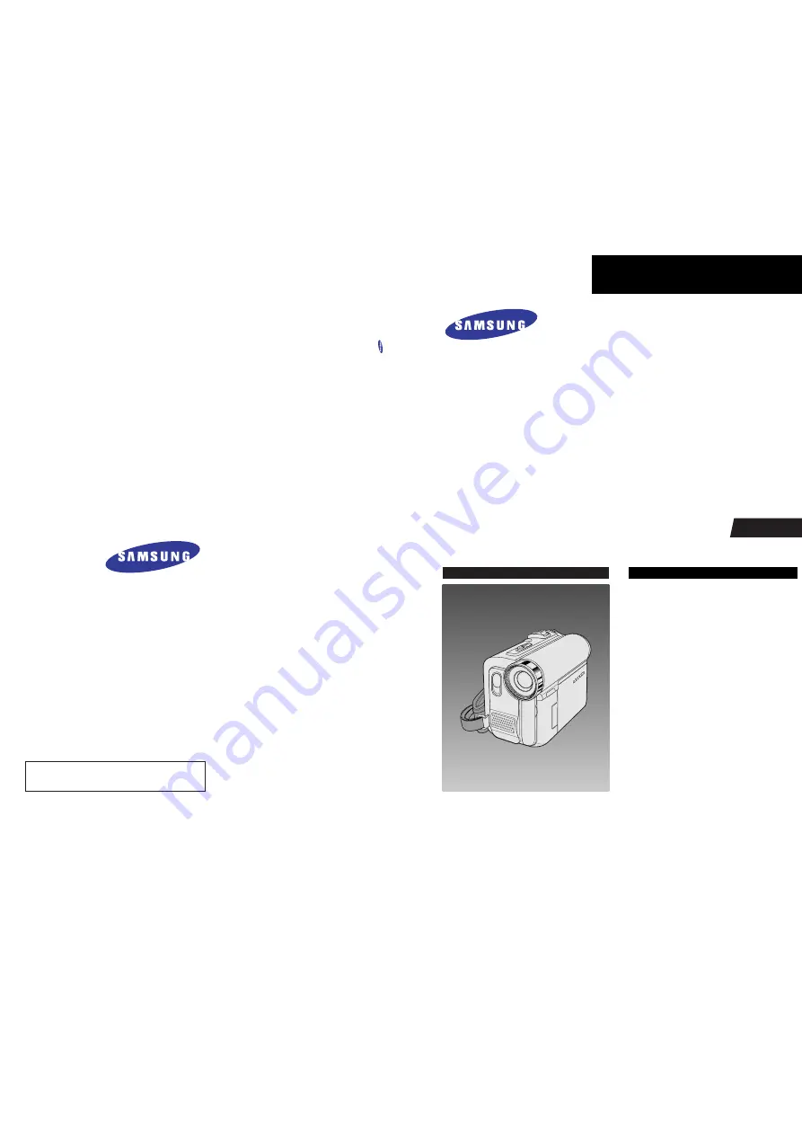
DIGITAL VIDEO CAMCORDER

Chassis : Tiger 

BASIC : VP-D455

Application Models 

: VP-D451(

I

)/VP-D453(

I

)/

VP-D454(

I

)/VP-D455(

I

)/

VP-D452B

I

/VP-D6650

I

VP-D6640

I/

VP-D6620

I

Application Area

XEF, XEU, XEG, XET, XEV, XEC, XSA, CDM, 

XST, XEO, XEH, XEP, XEE, EAP, EUR, XEN, 
HACO, TAW, TIT, COL, SEO, XSS, SED, XSH,
XSG, FES, XTL, CHN, ZAM, STS, SMR, XFA, 
ITN, KNT, XSE, FPT, RAD, AND, UMG, AFR

SERVICE 

Ultra Compact Design DVC

Use Built-in Flash Memory 

(VP-D454(i)/D455(i)/D6650

I

Only)

Multi Memory Card Slot

(VP-D454(i)/D455(i)/D6650

I

Only)

Direct Print System : PictBridge ™

USB 2.0

High quality MPEG4

Digital Image Stabilizer

Real Wide mode (16:9)

Manual 

DIGITAL VIDEO CAMCORDER

Merit & Character regarding Product

SERVICE MANUAL

VP-D451(

I

)/D452B

I

/D453(

I

)/D454(

I

)/D455(

I

)/D6620

I

/D6640

I

/D6650

I

ELECTRONICS

© Samsung Electronics Co., Ltd. 

FEB. 2005

Printed in Korea

AD82-00104A

This Service Manual is a property of Samsung Electronics Co .,Ltd.
Any unauthorized use of Manual can be punished under applicable

International and/or domestic law.

Summary of Contents for VP-D455

Page 1: ...Flash Memory VP D454 i D455 i D6650I Only Multi Memory Card Slot VP D454 i D455 i D6650I Only Direct Print System PictBridge USB 2 0 High quality MPEG4 Digital Image Stabilizer Real Wide mode 16 9 Man...

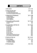
Page 2: ...Reassembly 4 1 4 16 4 1 Cabinet and PCB 4 1 4 2 Deck 4 5 5 Exploded View and Parts List 5 1 5 20 5 1 Ass y Chassis 5 2 5 2 Ass y Left 5 4 5 3 Ass y LCD 5 6 5 4 Ass y Right 5 8 5 5 Ass y Rear 5 10 5 6...

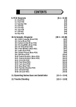
Page 3: ...in PCB 10 5 10 5 DV 1Chip Main PCB 10 6 10 6 Video Interface Main PCB 10 7 10 7 Audio Main PCB 10 8 10 8 Camera Process Main PCB 10 9 10 9 DSP Main PCB 10 10 10 10 Camera Memory 1 Main PCB 10 11 10 11...

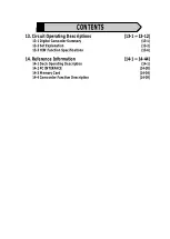
Page 4: ...Camcoder Summary 13 1 13 2 Set Explanation 13 2 13 3 H W Function Specifications 13 6 14 Reference Information 14 1 14 44 14 1 Deck Operating Description 14 1 14 2 PC INTERFACE 14 30 14 3 Memory Card...

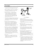
Page 5: ...t exceed 0 5 milliamp Reverse the power plug prongs in the AC outlet and repeat the test 6 X ray Limits The picture tube is designed to prohibit X ray emissions To ensure continued X ray protection re...

Page 6: ...instrument s ground lead to the instrument chassis ground before connecting the positive lead always remove the instrument s ground lead last 17 Observe the original lead dress especially near the fol...

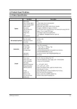
Page 7: ...pprox 18 83mm s LP approx 12 57mm s SP 60 minutes when using DVM 60 LP 90 minutes when using DVM 60 Approx 150 sec using DVM60 tape CCD Charge Coupled Device 800k pixels F1 8 10x Optical 900x Digital...

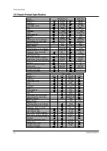
Page 8: ...dio Color Color Viewfinder 2 5 123K 2 5 123K LCD 680K 680K CCD 10x 900x 10x 900x Zoom Digita l Zoom 520 line 520 line Resolution MiniDV MiniDV Form at VM F830 D457 SC D455 D453 Model cod e NTSC Rsx NT...

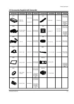
Page 9: ...Power Adapter AA E8 TYPE AD44 00090A AD68 00839G 5 Instruction Book 6 Lithium Battery CR2025 AD43 10130H 7 Remote Control AD59 00085A AD97 07354B 8 USB Cable AD39 00073A AD46 00082A AD46 00061A 9 Sof...

Page 10: ...Product Specification 2 4 Samsung Electronics MEMO...

Page 11: ...tment step In order to exit the adjustment mode disconnect the power source 2 Function of each buttons on the Set Key Buttons Description MENU Selector push Confirm Stores changed value in the adjustm...

Page 12: ...the power must be reset This can be done by disconnecting and reconnecting the power source Fig 3 2 Indicates current adjustment item Adjustment value For Engineering Mode Stored value Fig 3 3 3 1 2...

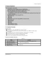
Page 13: ...CB Lens Zoom Track Zoom VR Center Auto HALL Auto IRIS Auto White Balance indoor Auto White Balance outdoor 3 2 1 Adjustment Preparation 1 Before you start Use the buttons on the CAMCORDER when adjusti...

Page 14: ...onitor OSD appears as shown Fig 3 5 the adjustment mode has been activated successfully Move the MENU Selector to highlight CAM ADJ and push the MENU Selector Monitor OSD shows Fig 3 6 Then Camera adj...

Page 15: ...range it shall be in focus The location of a focus lens is moving depending on the location of Zoom Lens During adjusting micom measures the focus location from a near distance to a long Camera is set...

Page 16: ...f in 00BC 00BD and 00BB respectively The OSD shows OK after finishing the adjustment The word OK is displayed for only a fraction of a second 6 Auto White Balance indoor Camera mode 3100 K gray scale...

Page 17: ...ment step In order to exit the adjustment mode disconnect the power source 2 Function of each buttons on the Set Key Buttons Description MENU Selector push Confirm Stores changed value in the adjustme...

Page 18: ...tment mode has been activated successfully Move the MENU Selector to highlight VCR ADJ and push the MENU Selector Monitor OSD shows Fig 3 10 Then VCR adjustment mode has been activated successfully ST...

Page 19: ...short Refer to Fig 3 11 two short point Press a STOP button for 3 seconds or more until INT OK appears See Fig 3 12 Fig 3 12 You continuously let two solder lands short until completing all adjustmen...

Page 20: ...B0 04 95 95 95 95 05 1F 1F 1F 1F 06 5A 5A 5A 5A 07 40 40 40 40 08 00 00 00 00 09 40 40 40 40 0A 90 90 90 90 0B 2A 2A 2A 2A 0C 30 30 30 30 0D A1 A1 A1 A1 0E 4C 4C 4C 4C 0F 10 10 00 0 00 0 10 05 05 05 0...

Page 21: ...the PLAY Key Cover the Top End sensor with black tape because they do not operate Note For the removal of the Housing Ass y refer to 4 2 2 page 4 6 Connceted the Recorder Circuit SWITCH C IN Fig 3 13...

Page 22: ...counterclockwise by hand Note Do not rotate the motor by power or rotate the Upper Drum assembly clockwise Also the Head tip will be damaged if the lens tissue is moved in a perpendicular direction Be...

Page 23: ...e tip of a 2mm stick as shown in Fig 3 16 Table 3 7 Fig 3 16 O Cleaning Oil Confirmation Tape path system D R I V I N G S Y S T E M Never let oil get on to the tape path surface Maintenance checks Hou...

Page 24: ...e between external surface of Holder Loading and extenal diamater of Arm Tension is 0 7 0 3mm Fig 3 17 If necessary proceed to step 4 If the Arm Tension is located inside or right the position specifi...

Page 25: ...B REV Torque check 1 Set up the cassette torque tape 2 Set to CAMERA mode Push the EDIT button and check that the torque value of Reel T is 9 3g cm 3 Push the EDIT button and check that the torque val...

Page 26: ...n oscilloscope Play back the alignment tape Check that the waveform of the RF signal is flat at both inlet and outlet A in Fig 3 21 If not flat B or C in Fig 3 21 do adjustments 3 4 5 b through 3 4 5...

Page 27: ...3 4 5 c Take Up Path Adjustment Play back the alignment tape and confirm that the tape is not twisted between the Guide Roller T and Capstan If the tape is twisted turn P8 Fig 3 23 Set to REV mode and...

Page 28: ...Fig 3 26 2 CUE and REV Check Playback the alignment tape and set to REV mode Confirm that the waveform peaks have a uniform Pitch Fig 3 27 A If the track pitch is not uniform do section 3 4 5 b Track...

Page 29: ...inch Roller Fig 3 28 Run the tape in CUE REV and FF REW modes then playback Confirm the waveform of PB RF signal rises flat within 3 seconds Also confirm that the tape is not twisted or curled around...

Page 30: ...3 20 Alignment and Adjustments Samsung Electronics MEMO...

Page 31: ...E 1 SCREW M 1 7 X 4 BLK ROTATE CASE TOP Fig 4 1 Ass y Top Removal 4 1 2 Ass y Front Removal Fig 4 2 Ass y Front Removal REMOVE 1 SCREW M1 7 X 2 BLK REMOVE 1 SCREW M1 7 X 4 WHT REMOVE 1 SCREW M1 7 X 4...

Page 32: ...eft Removal 4 1 4 Ass y LCD CVF Jack Removal Caution Please indicate that the connectors must be detached before separating the EASY Q Assembly Caution Please indicate that the connectors must be deta...

Page 33: ...the connectors must be detached before separating the Rear Assembly Fig 4 5 Ass y Rear Removal 4 1 6 Ass y Right Removal Fig 4 6 Ass y Right Removal REMOVE 2 SCREWS M1 7 X 2 BLK REMOVE 2 SCREWS M1 7 X...

Page 34: ...VE 3 SCREWS M1 7 X 2 WHT REMOVE Deck FPC 3 Point Caution Please indicate that the connector must be detached before separating the Deck Assembly from the MAIN PCB 4 1 8 Ass y Lens Removal REMOVE 2 SCR...

Page 35: ...he power supply output to approximately 3V 5V and connect it to the Motor Loading 2 Choose the polarity depending on whether loading or unloading See Table 4 1 3 Supply the voltage to the Motor Loadin...

Page 36: ...ding 1 Push the Lever see arrow A Detail A turn the Lever Lock in the direction of arrow B and open the Housing Ass y 2 Separate the Hook L and Hook R and then lift it 3 Separate the Shape of Pin L an...

Page 37: ...the 2 Screws then lift the Cover Reel Ass y 2 Then lift the Idler Ass y 4 2 3 b Reassembly 1 Fit the Idler Ass y into the Pin 2 Mount the Cover Reel Ass y to the Sub Chassis in the reverse direction...

Page 38: ...y Reel Disk S 4 2 4 b Reassembly 1 Mount the Reel Disk S 2 After pushed Arm Tension Ass y in the direction A and then insert into the Pin 3 Insert the Washer Slit and then hang the Spring Tension to...

Page 39: ...Sub Chassis Ass y from Main Chassis Fig 4 13 Sub Chassis 4 2 5 b Reassembly 1 Insert PinPart of Sub Chassis Ass y to Main Chassis Rail and then fit the reassembly part of two place to Secure Hole of...

Page 40: ...the post 4 2 6 a Disassembly 1 After turned Arm Review in the direction of arrow A and then lift up 2 Lift up the Reel Disk T 3 Lift up the Brake T PIN REEL DISK T BRAKE T ARM REVIEW PIN PIN 4 2 6 b R...

Page 41: ...ng or reassembling the Drum 1 Remove 1 Screw and then remove the Spring Plate Drum 2 Lift up the Drum 3 Remove 1 Screw and then lift up the Holder FPC 4 2 7 b Reassembly 1 Mount and insert the Drum to...

Page 42: ...ider Roller S and T 3 SCREWS GUIDE RAIL ASS Y GUIDE ROLLER S GUIDE ROLLER T POLE BASE S POLE BASE T MAIN CHASSIS 4 2 8 b Reassembly 1 Assembly the Guide Roller S and T as turn to countclock wise to th...

Page 43: ...bly 1 After assemble and fit Gear Tension Gear Cam Main to assemble point and then secure the 2 Screws 2 Insert Hook of Motor Loading Ass y to assemble point of Main Chassis and then secure the 1 Scre...

Page 44: ...apstan Arm Pinch Roller Slide Main LeverEject 2 SCREWS MOTOR CAPSTAN WASHER SLIT SPRING LEVER PINCH LEVER EJECT MAIN CHASSIS HOOK ARM PINCH ROLLER SLIDE MAIN MAIN CHASSIS DETAIL 4 2 10 a Disassembly N...

Page 45: ...r Capstan 2 Separate the Belt Timming lift the Gear Pully Fig 4 19 Gear Pully Belt Timming Gear Capstan WASHER SLIT GEAR CAPSTAN BELT TIMING GEAR PULLY 4 2 11 b Reassembly 1 Mount the Gear Pully and h...

Page 46: ...4 16 Disassembly and Reassembly Samsung Electronics MEMO...

Page 47: ...y Chassis 5 2 5 2 Ass y Left 5 4 5 3 Ass y LCD 5 6 5 4 Ass y Right 5 8 5 5 Ass y Rear 5 10 5 6 Ass y CVF 5 12 5 7 Ass y Case Left 5 13 5 8 Ass y Front 5 14 5 9 Ass y Housing 5 15 5 10 Mechanical Parts...

Page 48: ...Exploded View and Parts List 5 2 Samsung Electronics 5 1 Ass y Chassis C050 W225 P155 W121 W125 FL515 P052 P051 C314 C310 W121 C201 P001 W206 M001...

Page 49: ...ASSY MAIN BOARD TIGER PJ VP D455 XE 1 SA P051 AD97 09378A ASSY LENS ZOOM PC SSCL 10X 1 SA P052 AD29 00031A FILTER OLPF SSCL 4 5 3 4 1 60 1 SA P155 AD97 08613A ASSY THETA2 DECK FPC ASSY FPC THETA 1 SA...

Page 50: ...Exploded View and Parts List 5 4 Samsung Electronics 5 2 Ass y Left W112 P054 C550 C023 W297 FL433 P004 P157 W113 C696 C697 W113 W121 P158 P006 W112 C321 C001 L001...

Page 51: ...VP D455 PAL 1 SA P004 AD97 09593A ASSY FUNCTION BOARD TIGER PJ SC D45 1 SA P006 AD97 09596A ASSY JACK BOARD TIGER PJ SC D455 XA 1 SA P054 AD97 04289A ASSY SPEAKER D5 PJ G 17S08 0823 1 SA P157 AD97 096...

Page 52: ...Exploded View and Parts List 5 6 Samsung Electronics 5 3 Ass y LCD W298 L016 L017 W313 L014 W124 L011 L006 W118 W298 L013 C349 L0533 L004 C208 L015...

Page 53: ...TIGER PJ ABS94HB T1 1 SA L015 AD63 00733A COVER HINGE BOTTOM TIGER PJ ABS94HB 1 SA L016 AD97 09662A ASSY HINGE ASSY TIGER PJ 1 SA L017 AD97 09723A ASSY LCD FPC TIGER ASSY LCD FPC 1 SA L0533 AD07 00046...

Page 54: ...Exploded View and Parts List 5 8 Samsung Electronics 5 4 Ass y Right C659 C014 C010 W127 C698 C020 C018 C308 W241 C016 C019 W118 C660 W126 C661 W126 C210 C059 W126 C334 C212...

Page 55: ...SUS301 1 1 SA C308 AD61 02047A PLATE SPRING POWER TIGER PJ SUS301 1 SA C334 AD63 00739A COVER DC JACK TIGER PJ ABS94HB T1 0 1 SA C659 AD61 02017A BRACKET RIGHT A TIGER PJ SUS301 1 2 1 SA C660 AD61 02...

Page 56: ...Exploded View and Parts List 5 10 Samsung Electronics 5 5 Ass y Rear W112 FL512 P009 W118 P159 W222 P101 C556 C208 C042 C663 C306 C666 C044 C664 C665 W112...

Page 57: ...SUS301 1 1 SA C308 AD61 02047A PLATE SPRING POWER TIGER PJ SUS301 1 SA C334 AD63 00739A COVER DC JACK TIGER PJ ABS94HB T1 0 1 SA C659 AD61 02017A BRACKET RIGHT A TIGER PJ SUS301 1 2 1 SA C660 AD61 02...

Page 58: ...ASSY UNIT CVF ASSY TIGER PJ 1 SA L064 AD41 00683A FPC CVF TIGER PJ REV 00 POLYESTER 2 1 SA W118 6003 001291 SCREW TAPTITE CH B M1 4 L3 0 ZPC 2 SA W121 6002 001132 SCREW TAPPING BH T0 5 2 M1 7 L3 0 1...

Page 59: ...A ASSY TRIPOD ASSY TIGER PJ 1 SA P091 AD97 09715A ASSY CASE LEFT ASSY TIGER PJ MULTI 1 SA W296 6003 001479 SCREW TAPTITE BH B M1 7 L4 ZN 2 SA Exploded View and Parts List 5 13 Samsung Electronics 5 7...

Page 60: ...5C ASSY FRONT BOARD TIGER PJ SC D457 X 1 SA P121 AD97 09713A ASSY CASE FRONT ASSY TIGER PJ LIGHT 1 SA W127 6003 001292 SCREW TAPTITE CH 0 3 B M1 7 L3 Z 6 SA Exploded View and Parts List 5 14 Samsung E...

Page 61: ...39A INLAY DECORTION TIGER PJ PC T1 0 W7 1 SA W116 6001 001527 SCREW MACHINE CH 0 3 M1 7 L2 0 N 4 SA W119 6001 001444 SCREW MACHINE PH M1 7 L2 0 ZPC BL 4 SA W127 6003 001292 SCREW TAPTITE CH 0 3 B M1 7...

Page 62: ...View and Parts List 5 16 Samsung Electronics 5 10 Mechanical Parts Main Chassis M010 M026 W105 M011 M013 W106 M020 M019 W107 M021 M016 M018 W101 W104 W103 M022 W106 M012 M202 M023 M017 M024 M203 M025...

Page 63: ...SSY GUIDE ROLLER Mold ETC DD 4 P 1 SNA M021 AD61 01483A GUIDE ROLLER DD 4 POM BLACK M 1 SNA M022 AD61 00558A PLATE S P BASE DD 3 SUS632 CSP T0 1 SA M023 AD66 00221A PULLEY BELT TIMING DD 4 POLYURETHAN...

Page 64: ...Exploded View and Parts List 5 18 Samsung Electronics 5 11 Mechanical Parts Sub Chassis M030 M033 M037 M203 M036 W101 M042 M041 M040 M039 M031 M032 M035 M038 M034 W102 M044 M043...

Page 65: ...DD 4 SUS304 WPB 1 SA M038 AD97 06402A ASSY ARM REVIEW DD 4 ASSY 1 SA M039 AD97 07213A ASSY BRAKE SOFT S DD 4 ASSY 1 SNA M040 AD97 06394A ASSY HOUSING SECC ETC DD 4 ASSY 1 SA M041 AD61 01194A HOUSING L...

Page 66: ...Exploded View and Parts List 5 20 Samsung Electronics MEMO...

Page 67: ...00NF 10 10V X7R TP 100 1 SA C221 2203 000254 C CER CHIP 10nF 10 16V X7R 1005 1 SA C222 2203 006006 C CER CHIP 0 005NF 0 25PF 50V C0G 1 SA C223 2203 006006 C CER CHIP 0 005NF 0 25PF 50V C0G 1 SA C224 2...

Page 68: ...1nF 10 50V X7R 1005 1 SA C717 2203 000254 C CER CHIP 10nF 10 16V X7R 1005 1 SA C718 2203 000254 C CER CHIP 10nF 10 16V X7R 1005 1 SA C719 2203 006320 C CER CHIP 2200nF 10 16V X7R TP 20 1 SA C721 2404...

Page 69: ...5 1 SA CP305 2203 001432 C CER CHIP 47nF 80 20 16V Y5V 100 1 SA CP306 2203 000438 C CER CHIP 1nF 10 50V X7R 1005 1 SA CP307 2203 000714 C CER CHIP 3 3nF 10 50V X7R TP 100 1 SA CP33 2203 006048 C CER C...

Page 70: ...X2 NPN 150MW EMT6 1 SA Q723 0501 000225 TR SMALL SIGNAL 2SC4617 NPN 200mW E 1 SA QP01 0501 000225 TR SMALL SIGNAL 2SC4617 NPN 200mW E 1 SA QP05 0504 001025 TR DIGITAL DTC143EE NPN 150MW 4 7K 1 SA R101...

Page 71: ...1 16W TP 1005 1 SA R506 2007 000140 R CHIP 1Kohm 5 1 16W TP 1005 1 SA R507 2007 000162 R CHIP 100Kohm 5 1 16W TP 1005 1 SA R508 2007 000140 R CHIP 1Kohm 5 1 16W TP 1005 1 SA R509 2007 000162 R CHIP 1...

Page 72: ...0162 R CHIP 100Kohm 5 1 16W TP 1005 1 SA R558 2007 000140 R CHIP 1Kohm 5 1 16W TP 1005 1 SA R559 2007 000140 R CHIP 1Kohm 5 1 16W TP 1005 1 SA R5601 2007 000162 R CHIP 100Kohm 5 1 16W TP 1005 1 SA R56...

Page 73: ...5 1 16W TP 1005 1 SA R799 2007 000151 R CHIP 15Kohm 5 1 16W TP 1005 1 SA RA50 2007 000148 R CHIP 10Kohm 5 1 16W TP 1005 1 SA RA51 2007 000157 R CHIP 47Kohm 5 1 16W TP 1005 1 SA RA52 2007 000157 R CHI...

Page 74: ...5 2007 000171 R CHIP 0ohm 5 1 16W TP 1005 1 SA W125 6001 001385 SCREW MACHINE CH M1 7 L2 5 ZPC BL 5 SA W225 6009 001410 SCREW SPECIAL CH M1 4 L4 7 2 5 3 SA X201 2801 003703 CRYSTAL SMD 24 576MHz 50ppm...

Page 75: ...1 SA RF62 2007 000102 R CHIP 100Kohm 5 1 10W TP 1608 1 SA RF65 2007 000402 R CHIP 150ohm 5 1 10W TP 1608 1 SA RF66 2007 000402 R CHIP 150ohm 5 1 10W TP 1608 1 SA RF67 2007 000402 R CHIP 150ohm 5 1 10...

Page 76: ...56 R CHIP 6 2Kohm 5 1 10W TP 1608 1 SA RR20 2007 000651 R CHIP 27Kohm 1 1 10W TP 1608 1 SA RR21 2007 000923 R CHIP 470Kohm 1 1 10W TP 1608 1 SA RR22 2007 000563 R CHIP 220Kohm 1 1 10W TP 1608 1 SA SWR...

Page 77: ...AD61 01048A PLATE TERMINAL BRM D2A NIKEL T0 2 1 SNA AD63 00208A TERMINAL LI BRM D2 BRM E1 WL 85 1 SNA AD64 00492A CASE BOTTOM REMOCON BRM D2 ABS 1 SNA AD64 00867A CABINET TOP REMOCON BRM D2A 1 SNA AD...

Page 78: ...TE CH 0 3 B M1 7 L3 Z 2 SA W127 6003 001292 SCREW TAPTITE CH 0 3 B M1 7 L3 Z 1 SA W127 6003 001292 SCREW TAPTITE CH 0 3 B M1 7 L3 Z 1 SA W127 6003 001292 SCREW TAPTITE CH 0 3 B M1 7 L3 Z 7 SA W127 600...

Page 79: ...ns DSP6 S5C7376X MULTI Memory Slot MULTI Stick Slot TMP1962 24C045STP XC61FC2512 RS5C372A MAIN MICOM E2PROM RESET TIMER SONY LCO 2 5 123K SONY CVF 0 24 77K Link Phy Layer ECC MOD DEMOD DCT IDCT COMP D...

Page 80: ...AIN Control Loop Filter Gain Loop Filter Timing Viterbi DAC225 DAC45 ATFout TEST_analog PB_CLK PB_DATA NCO PLL VCO System Clock 45MHz Function Control Function Control Fix Filter Interpolator BPF HPF...

Page 81: ...MPEG4 CODEC 30FPS VGA JPEG CODEC VIDEOBUS AHB BUS ARM920T AHB2VIDEO BRIDGE APB BUS AHB2APB BRIDGE USB2 0 DEV UART 2 AUDIO CODEC G 726 MSPro SD MMC Timer 4 GPIO 32bit DNIe DMA 4 DVC DSP I2C 2 Motor Co...

Page 82: ...MPEG4 CODEC 30FPS VGA JPEG CODEC VIDEOBUS AHB BUS ARM920T AHB2VIDEO BRIDGE APB BUS AHB2APB BRIDGE USB2 0 DEV UART 2 AUDIO CODEC G 726 MSPro SD MMC Timer 4 GPIO 32bit DNIe DMA 4 DVC DSP I2C 2 Motor Co...

Page 83: ...Samsung Electronics 8 1 8 Wiring Diagram MEMORY STICK VP D453 I D6620I VP D454 I D455 I D6650I...

Page 84: ...Wiring Diagram 8 2 Samsung Electronics MEMO...

Page 85: ...Samsung Electronics 9 1 9 PCB Diagrams 9 1 Main PCB 9 2 9 2 Front PCB 9 6 9 3 Function PCB 9 6 9 4 CVF PCB 9 7 9 5 CCD PCB 9 7 9 6 Jack PCB 9 8 9 7 LCD PCB 9 8 9 8 Rear PCB 9 9 Page...

Page 86: ...PCB Diagrams 9 2 Samsung Electronics 9 1 Main PCB COMPONENT SIDE...

Page 87: ...PCB Diagrams Samsung Electronics 9 3 L708 L704 L706 L717 L719...

Page 88: ...PCB Diagrams 9 4 Samsung Electronics CONDUCTOR SIDE Fuse 1 25A 32V...

Page 89: ...PCB Diagrams Samsung Electronics 9 5 XM01 54MHz XM02 48MHz X201 24 576M X202 41 85M X501 13 5MHz X502 32 768KHz Fuse 1 25A 32V...

Page 90: ...PCB Diagrams 9 6 Samsung Electronics 9 2 Front PCB COMPONENT SIDE CONDUCTOR SIDE 9 3 Function PCB COMPONENT SIDE CONDUCTOR SIDE...

Page 91: ...PCB Diagrams Samsung Electronics 9 7 9 4 CVF PCB COMPONENT SIDE CONDUCTOR SIDE 9 5 CCD PCB COMPONENT SIDE CONDUCTOR SIDE...

Page 92: ...PCB Diagrams 9 8 Samsung Electronics 9 6 Jack PCB COMPONENT SIDE CONDUCTOR SIDE 9 7 LCD PCB COMPONENT SIDE CONDUCTOR SIDE...

Page 93: ...PCB Diagrams Samsung Electronics 9 9 9 8 Rear PCB COMPONENT SIDE CONDUCTOR SIDE Rear PCB CNR02 2 3Pin Rear PCB CNR02 7Pin Rear PCB CNR02 9Pin UART_TXD ENVE Head SW UART_RXD...

Page 94: ...PCB Diagrams 9 10 Samsung Electronics MEMO...

Page 95: ...ar PCB 10 16 10 16 Function Function PCB 10 17 10 17 CVF CVF PCB 10 18 10 18 LCD LCD PCB 10 19 For schematic Diagram Resistors are in ohms 1 8W unless otherwise noted Note Special note Most semiconduc...

Page 96: ...Schematic Diagrams 10 2 Samsung Electronics This Document can not be used without Samsung s authorization 10 1 DC DC Converter Main PCB...

Page 97: ...Schematic Diagrams Samsung Electronics 10 3 This Document can not be used without Samsung s authorization 10 2 Servo Main PCB...

Page 98: ...Schematic Diagrams 10 4 Samsung Electronics This Document can not be used without Samsung s authorization FROM TO TEST JIG 10 3 System Control Main PCB...

Page 99: ...Schematic Diagrams Samsung Electronics 10 5 This Document can not be used without Samsung s authorization 10 4 Pre Amp PRML Main PCB...

Page 100: ...Schematic Diagrams 10 6 Samsung Electronics This Document can not be used without Samsung s authorization 10 5 DV 1Chip Main PCB...

Page 101: ...Schematic Diagrams Samsung Electronics 10 7 This Document can not be used without Samsung s authorization 10 6 Video Interface Main PCB...

Page 102: ...Schematic Diagrams 10 8 Samsung Electronics This Document can not be used without Samsung s authorization 10 7 Audio Main PCB...

Page 103: ...Schematic Diagrams Samsung Electronics 10 9 This Document can not be used without Samsung s authorization 10 8 Camera Process Main PCB...

Page 104: ...Schematic Diagrams 10 10 Samsung Electronics This Document can not be used without Samsung s authorization 10 9 DSP Main PCB...

Page 105: ...Schematic Diagrams Samsung Electronics 10 11 This Document can not be used without Samsung s authorization 10 10 Camera Memory 1 Main PCB...

Page 106: ...Schematic Diagrams 10 12 Samsung Electronics This Document can not be used without Samsung s authorization 10 11 Camera Memory 2 Main PCB...

Page 107: ...Schematic Diagrams Samsung Electronics 10 13 This Document can not be used without Samsung s authorization FROM TO CAMERA PROCESS CNP01 10 12 CCD CCD PCB...

Page 108: ...Schematic Diagrams 10 14 Samsung Electronics This Document can not be used without Samsung s authorization FROM TO AUDIO CN601 10 13 Front Front PCB...

Page 109: ...Schematic Diagrams Samsung Electronics 10 15 This Document can not be used without Samsung s authorization FROM TO VIDEO INTERFACE CN302 10 14 Jack Jack PCB...

Page 110: ...Schematic Diagrams 10 16 Samsung Electronics This Document can not be used without Samsung s authorization FROM TO PRODDUCT JIG FROM TO DC DC CN702 10 15 Rear Rear PCB...

Page 111: ...Schematic Diagrams Samsung Electronics 10 17 This Document can not be used without Samsung s authorization FROM TO VIDEO INTERFACE CN301 10 16 Function Function PCB...

Page 112: ...Schematic Diagrams 10 18 Samsung Electronics This Document can not be used without Samsung s authorization FROM TO FUNCTION CNF05 FROM TO CVF PANEL 10 17 CVF CVF PCB...

Page 113: ...Schematic Diagrams Samsung Electronics 10 19 This Document can not be used without Samsung s authorization 10 18 LCD LCD PCB...

Page 114: ...Schematic Diagrams 10 20 Samsung Electronics This Document can not be used without Samsung s authorization MEMO...

Page 115: ...i D454 i D455 i only EASY Q REW REC SEARCH REV FF REC SEARCH FWD PLAY STILL FADE S SHOW SLIDE SHOW STOP BLC MULTI ENGLISH Getting to Know Your Camcorder 13 13 Front Left View 1 Lens 2 LED Light see pa...

Page 116: ...RESET button Memory Card Slot Usable Memory Card VP D453 i only Memory Stick Memory Stick PRO VP D454 i D455 i only Memory Stick Memory Stick PRO SD MMC ENGLISH Getting to Know Your Camcorder 15 15 R...

Page 117: ...he amount of continuous recording time available depends on The type and capacity of the Battery pack you are using How often the zoom function is used It is recommended that you have several batterie...

Page 118: ...aranteed for all computer environments recommended above The IEEE1394 cable DV cable is sold separately Video Capture software is commercially available Most DV enabled PCs have a 6 pin socket In this...

Page 119: ...a transfer will stop and the data may be damaged If you connect the USB cable to a PC using a USB HUB or with other devices at the same time it may cause conflict and may not work properly If this occ...

Page 120: ...ormal Approx 74 Approx 148 Selecting the Image Quality Move Select Exit MENU M Cam Mode Back Photo Quality File No Super Fine Series Move Select Exit MENU M Cam Mode Memory Photo Quality File No Super...

Page 121: ...tronics 12 1 12 Troubleshooting Loading Emergency Is Loading normal IC401 57Pin VS_L 4 8V IC401 25Pin VCC1 4 5V STOP REPAIR IC501 MICOM Changing Loading Motor DECK Housing close CHECK L727 3V NO NO NO...

Page 122: ...oes Not Rotate IC401 16Pin 3V IC401 5Pin is VS_D 4 8V IC401 is Drum U V W Waveform REPAIR IC501 MICOM Is DRUM error OUT normal CHECK Q702 L717 Changing Drum Motor REPAIR IC401 CHECK R5108 R5107 C518 C...

Page 123: ...ics 12 3 Capstan Does Not Rotate IC401 2 3V IC401 44 is VS normal IC401 is CAP U V W normal CHECK IC501 MICOM Is CAPSTAN error OUT normal CHECK Q701 L719 Changing CAP MOTOR CHECK IC401 CHECK IC501 ALL...

Page 124: ...IN TO JACK BOARD CHANGE DSP6 ICM01 CHANGE CAMERA CHANGE THE FFC REPAIR IC201 AND THE AROUND THE CIRCUIT END OF REPAIR IC301 3 5Pin is Y C signal normal REPAIR IC301 NO YES NO YES NO YES NO YES NO YES...

Page 125: ...al Is Circuit around IC101 IC201 normal Is Video in out Terminal normal CHECK THE HEAD OF DRUM REPAIR THE IC101 IC201 CHANGE THE VIDEO IN OUT JACK REPAIR THE IC301 END OF REPAIR IC301 8 14Pin Is Y C s...

Page 126: ...THE CIRCUITRY AROUND THE MICOM NO YES YES CHECK L704 L706 L708 L710 L712 L714 L717 L719 NO YES CHECK L701 L702 NO YES CHANGE TR NO YES Q701 Q708 4 5Pin is the output vlotage output when power is suppl...

Page 127: ...Speak Connector FPC Harness normal IC201 is AUDIO VCO Normal REPAIR THE CONNECTOR FPC HARNESS CHECK AUDIO POWER L601 L602 L603 L604 NO CHECK THE CONSTANT AND WRONG SOLDERING CHECK THE CONSTANT AND WR...

Page 128: ...Troubleshooting 12 8 Samsung Electronics MEMO...

Page 129: ...ich applied FM method digital videos use PCM method to achieve high sound quality of MD standard 3 Can challenge multimedia system by connecting with PC Can edit by using image edition software Image...

Page 130: ...g 13 2 Sector arrangement on helical track H2 H1 Tp 10um SUB CODE VIDEO AUDIO ITI Lr 32 89mm OPTIONAL TRACK We 5 24mm HO 5 8mm Wt 6 35mm TAPE a 9 1668 TAPE LOWER EDGE PRE4 1200bits PRE3 500bits PRE1 1...

Page 131: ...NE FRAME 480 576 5 ACTIVE LINE No FIELD1 23 262 285 524 FIELD2 23 310 335 622 6 quantum Y Cr Cb etc are by carrying out and they are 8bits straight lines quantum 7 A relation with level which scale 1...

Page 132: ...ack Porch Front porch 40IRE Ref Burst Amptd 4 IRE 2 0 IR E 4 IRE 7 5 IRE Z Z 0 7 Vpp 0 Vpp 0 15 Vpp 0 3 Vpp 100 0 3Vpp ntsc timing pal timing 10 9 s 0 2 s SYNC to Blanking End 9 4 s 1 s SYNC to Burst...

Page 133: ...Audio and video products Safety Assurance Regulation No 776 Adapter only Table 13 3 Safety FCC Part 15B USA Standard Class B Radio Frequency Devices EN 55013 Europe Standard EMI Part of CE EN 55020 EN...

Page 134: ...the Camera Lens Ass y with the audio signal in DV format on a 6 35 mm tape 13 3 2 Camera Circuit Block H W Function Specifications DSP6 receives the digitized CCD signal or ITU R656 data and outputs...

Page 135: ...ontrol 2 DV1 Chip Control PRML Control Audio Control 3 Input control for Function Keys and Remote Control Keys 4 IEEE 1394 LCD CVF Control 5 Mechanism Control SERVO BLOCK controls the speed and phase...

Page 136: ...PRML BLOCK that processes the amplified signal to the appropriate digital video signal and DV1 Chip BLOCK that processes both the input signal from Camera Block and the signal read from a tape It also...

Page 137: ...ably play back by switching the signal to PB Clock when an unstable signal is received from the PREAMP It supplies 41 85 Mbps PB data to the DV 1 Chip after being provided with the playback output sig...

Page 138: ...e Block Diagram 13 3 6 AV IF Block H W Function Specifications Video Interface Block receives Video Y C that is included with OSD from the DV 1 Chip and then outputs AV Out and S Video Out through the...

Page 139: ...fications DC DC BLOCK produces and provides stable power to the each Block from 7 4V Battery power or 8 4V power adapter DC DC BLOCK controls a total of 7 kinds of voltage 2 5V drive CH1 5V drive CH4...

Page 140: ...Circuit Operating Description 13 12 Samsung Electronics MEMO...

Page 141: ...ASS Y MOTOR LOADING ASS Y GEAR WHEEL GEAR TENSION POLE BASE S ASS Y ARM TENSION ASS Y REEL DISK S ASS Y BRAKE SOFT S ASS Y COVER REEL BRAKE ASS Y HOLDER FPC DRUM ASS Y MOTOR CAPSTAN ASS Y GEAR CAPSTAN...

Page 142: ...s Fig 14 2 Bottom View BASE DRUM RAIL ASS Y MOTOR LOADING ASS Y GEAR WHEEL GEAR TENSION POLE BASE S ASS Y GEAR CAM MAIN GEAR PULLY HOLDER FPC MOTOR CAPSTAN ASS Y GEAR CAPSTAN POLE BASE T ASS Y ARM PIN...

Page 143: ...l 3 Modes signal 2 common Rotation Angle of Gear Mode Mechanical state EJECT 18k 68 5 46 6 Open Housing UNLOAD 36 4 4 Standby Cassette Down LD 1 54 51 59 Idler Rotate and stop in Loading Mode LD 2 72...

Page 144: ...ADING GEAR WORM MOTOR GEAR WORM LOADING GEAR WHEEL GEAR TENSION GEAR CAM MAIN 14 1 3 Operation 14 1 3 1 Gear Connecting 1 Moter Loading rotates Gear Worm Motor Gear Worm Loading 2 Gear Wheel rotates 3...

Page 145: ...ION PIN CAM GEAR CAM MAIN CHASSIS SUB 14 1 3 2 Chassis Sub 1 Motor Loading rotates 2 Gear Wheel rotates 3 Gear Tension rotates 4 Gear Cam Main rotates 5 Pin rotates 6 Chassis Sub moved by shape of Cam...

Page 146: ...D 1 LD 2 STOP PB MOTOR LOADING REEL DISK S BRAKE S CHASSIS SUB GERA CAM MAIN 14 1 3 3 Brake S Sub Main 1 Motor Loading rotates 2 Gear Cam Main rotates 3 Chassis Sub slides 4 Gear Cam Main continue rot...

Page 147: ...Loading rotates 2 Chassis Sub slides 3 Brake T separated or contacted Gear shape of Brake T by rotate direction of Reel Disk T Mode Brake Main T OFF ON EJECT UNLOAD LD 1 LD 2 STOP PB Fig 14 7 Brake T...

Page 148: ...PRING TENSION 14 1 3 5 Arm Tension 1 Motor Loading rotates 2 Chassis Sub slides 3 Arm Tension rotates in direction of arrow By force of Spring Tension and guide of Cam Curve A in Main Chassis 4 After...

Page 149: ...ch rotates by Cam Curve A of Chassis Sub 4 After Chassis Sub is finished loading Slider Main slides in direction of arrow 5 Pinch Roller contacts shaft of Motor Capstan 6 Motor Loading rotates in reve...

Page 150: ...LOADING CHASSIS MAIN CHASSIS SUB ARM REVIEW CAM CURVE 14 1 3 7 Arm Review 1 Motor Loading rotates 2 Chassis Sub moves 3 Arm Review simultaneously rotates clockwise and translates by Cam Curve of Chas...

Page 151: ...N GUIDE RAIL GEAR LOADING S GEAR LOADING T POLE BASE T 14 1 3 8 Pole Base S T 1 Motor Loading rotates 2 Gear Wheel rotates 3 Gear Tension rotates 4 Gear Cam Main rotates 5 Gear Loading S T rotates 6 P...

Page 152: ...R CAPSTAN GEAR CAPSTAN REEL DISK T BELT TIMMING GEAR PULLY DRUM 14 1 3 9 Reel Driving 1 Motor Capstan rotates 2 Gear Capstan rotates 3 Belt Timming transmits rotation to Gear Pully 4 Gear Idler engage...

Page 153: ...ssette lid lock Housing down Chassis Sub s Cover Stopper opens cassette lid Cassette in By Key Release of Cover reel releases Reel lock of Cassette tape Housing is locked by Lever Lock and Chassis Sub...

Page 154: ...inch Roller attaches to Capstan Shaft Brake S released from Reel S Motor Capstan rotates back ward silghtly and forward Pinch Roller rotates forward Pinch Roller rotates via Silder Main and detaches f...

Page 155: ...CH ROLLER REEL DISK T BRAKE T SWITCH MIC HOLDER FPC MOTOR CAPSTAN GEAR CAPSTAN POLE BASE T ARM PINCH ROLLER BELT TIMMING SLIDE MAIN LEVER EJECT MOTOR LOADING GEAR WHEEL GEAR TENSION POLE BASE S ARM TE...

Page 156: ...to Capstan Shaft which puts the tape between roller and Capstan Shaft Arm Tension is moved in direction of arrow by Gear Tension Cam Curve causing tension to tape Drum rotates forward Motor Capstan r...

Page 157: ...Fig 14 16 DRUM REEL DISK T SWITCH C IN BRAKE T HOLDER FPC MOTOR CAPSTAN ARM PINCH ROLLER GEAR CAPSTAN BELT TIMMING SLIDE MAIN GEAR PULLY LEVER EJECT MOTOR LOADING ARM TENSION REEL DISK S BRAKE S MOTO...

Page 158: ...tape between roller and Capstan Shaft Arm Tension is moved in direction of arrow by Cam curve of Gear Tension causing tension to tape Drum rotates foward Motor Capstan rotates forward Gear Capstan Bel...

Page 159: ...Fig 14 17 MOTOR LOADING ARM TENSION REEL DISK S BRAKE S MOTOR LOADING GEAR WHEEL GEAR TENSION GEAR CAM MAIN DRUM REEL DISK T SWITCH C IN BRAKE T HOLDER FPC MOTOR CAPSTAN ARM PINCH ROLLER GEAR CAPSTAN...

Page 160: ...using tension to tape Motor Capstan rotates reverse Gear Capstan Belt Timming Gear pully and Gear ldler rotate in order Reel totates 30 times faster than PLAY speed Reel S rotates 30 times faster than...

Page 161: ...MOTOR LOADING ARM TENSION REEL DISK S BRAKE S MOTOR LOADING GEAR WHEEL GEAR TENSION GEAR CAM MAIN DRUM REEL DISK T SWITCH C IN BRAKE T HOLDER FPC MOTOR CAPSTAN ARM PINCH ROLLER GEAR CAPSTAN BELT TIMM...

Page 162: ...in direction arrow by Cam of Switch Mode Motor Loading stops Pinch Roller rotates Motor Capstan rotates in reverse Gear Capstan Belt Timing Clutch and Gear ldler rotate in order Reel T rotates Reel S...

Page 163: ...Fig 14 19 MOTOR LOADING ARM TENSION REEL DISK S BRAKE S MOTOR LOADING GEAR WHEEL GEAR TENSION GEAR CAM MAIN DRUM REEL DISK T SWITCH C IN BRAKE T HOLDER FPC MOTOR CAPSTAN ARM PINCH ROLLER GEAR CAPSTAN...

Page 164: ...ch and Gear ldler rotate in order Arm Loading S T move in direction of arrow and Pole Base S T silde Tape is wound to cassette S W Push is turned off Reel T rotates Drum stops Motor Capstan stops Arm...

Page 165: ...PULLY BASE DRUM MOTOR LOADING GEAR WHEEL GEAR TENSION POLE BASE S ARM TENSION REEL DISK S BRAKE S COVER REEL POLE BASE T HOLDER FPC MOTOR CAPSTAN ARM PINCH ROLLER GEAR CAPSTAN BELT TIMMING SLIDE MAIN...

Page 166: ...5 times faster than PLAY mode Motor Capstan rotates approx 10 5 times faster than PLAY mode Gear Capstan Belt Timming Gear Pully Gear Idler rotate in order Reel T rotates approx 10 5 times faster tha...

Page 167: ...Reference Information Samsung Electronics 14 27 REEL DISK S GEAR IDLER DRUM MOTOR CAPSTAN GEAR CAPSTAN REEL DISK T BELT TIMMING GEAR PULLY Fig 14 21...

Page 168: ...s in reverse approx 9 5 times faster than PLAY mode Gear Capstan Belt timming Gear pully and Gear Idler rotate in order Reel T rotates in reverse approx 9 5 times faster than PLAY mode Reel S rotates...

Page 169: ...Reference Information Samsung Electronics 14 29 Fig 14 22 DRUM REEL DISK S GEAR PULLY MOTOR CAPSTAN GEAR CAPSTAN REEL DISK T GEAR IDLER BELT TIMMING...

Page 170: ...or a parallel port That leaves only 4 usable IRQs Nonetheless a USB can connect 127 peripherals for use at one IRQ It connects the mouse with the keyboard the keyboard with the printer etc as if to li...

Page 171: ...k layer chips Because it supports one of the most important characteristics of 1394 the isochronous transmission it ensures the bandwidth and transmission of the real time multimedia data or AV data A...

Page 172: ...it SIU It implements an endpoint address decoding for the USB packet 3 Endpoint Controls Endpoint 0 controller only implements a control transfer Other endpoints 1 3 can set up In Out randomly using t...

Page 173: ...ring 6 Internet Register Using of the indexing scheme by the internal register for the endpoint register is as follows IN_CSR IN Control Status Register OUT_CSR OUT Control Status Register IN_MAXP IN...

Page 174: ...rpose media F Recent standards have developed to meet the Description Developer Current Maximum Memory Capacity Size Width X Inside Diameter X Thickness In mm Number of Terminal pins or electrodes Cop...

Page 175: ...idely used MMC is mainly being used in Europe SmartMedia usage will be reduced in the future Memory Cards of Future Mainstream Currently Popular Devices Memory Stick Pro High Speed High capacity Memor...

Page 176: ...t features standard copyright protection technology Adapted copyright protection technology is CPRM Content Protection for Recordable Media which is being used for DVD s SD Memory Card slots are compa...

Page 177: ...er of interrupts and overheads in the process For an even faster method Direct Memory Access DMA adapted standard which is a method of existing hard disk data transfer is being researched DMA method r...

Page 178: ...Stick Duo as a conventional memory stick the dedicated conversion adapter should be used together For MMC which was already small there is also the RS MMC Reduced Size Multi Media Card that is half th...

Page 179: ...here is a bright light behind the object being shot Enables bright and clear shooting of objects that appear dark and shaded due to the backlight Tape rewind Fast forward Enables ordered viewing of st...

Page 180: ...t and the location Used for shooting with a fixed color tone regardless of the shooting location or the environment Used for shooting with the compensated color tone of indoor incandescent lighting Di...

Page 181: ...nserted when editing and recording on 1 track stereo audio of a high resolution image Audio Select Only the audio at the time of shooting is audible Only dubbed music and background music are audible...

Page 182: ...PAL 176X144 352X288 Can print out pictures from the memory card only used with the printers that are compatible with memory cards Photo Delete Protection Setup When it is set up photos cannot be delet...

Page 183: ...der Select video mode on the camcorder Play the video Then start recording after pushing the start recording button two times on the camcorder Recording TV to the camcorder Connect the audio video cab...

Page 184: ...Reference Information 14 44 Samsung Electronics MEMO...

Reviews: