Alignment and Adjustments
3-5
Samsung Electronics
3-2-2 Camera Adjustment
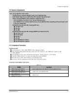
Note
: "XX XX" indicate the previous preset value and adjusted value.
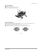
Press the “MENU Selector” (Confirm) to store the adjusted value.
Adjusted values
Stored values
Fig. 3-6
1) EEPROM Data Initialize
Caution
: These adjustments must be done when installing a new EPROM (IC105) or Main PCB.
Œ
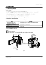
Press the “EASY-Q”(Mode Up)/”DISPLAY”(Mode Down) buttons until CAMADJ displays “0DF XX XX”.
´
Use the “MENU Selector” (Data Up/Down) until the display data for EVR is “A0”.
ˇ
Press the “MENU Selector” (Confirm).
¨
The OSD shows “OK” after finishing the initalize.
2) Lens Zoom Track
Caution
: For whole zoom range, it shall be in focus.
The location of a focus lens is moving depending on the location of Zoom Lens.
During adjusting, micom measures the focus location from a near distance to a long.
Œ
Camera is set to E-E mode.
´
Focus chart photo.
ˇ
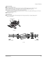
Center the camera about 3m from a focus chart which, should be placed on a flat surfaced white or gray wall.
¨
Connect the video output terminal to a TV.
ˆ
Press the “EASY-Q” (Mode Up)/”DISPLAY” (Mode Down) buttons until CAMADJ displays “0DE XX XX”.
Ø
Press the “MENU Selector” to begin adjustment.
The camera must be kept still when adjusting the zoom and focus lens.
If you don’t have any chart, you can use the object which has a lot of vertical line.
The OSD shows “OK” after finishing the adjustment.
(The word “OK” is displayed for only a fraction of a second.)
Fig. 3-7
3M
±
1cm
(Be sure to maintain the distance)
CCD
LENS
Summary of Contents for VP-D455
Page 10: ...Product Specification 2 4 Samsung Electronics MEMO...
Page 30: ...3 20 Alignment and Adjustments Samsung Electronics MEMO...
Page 46: ...4 16 Disassembly and Reassembly Samsung Electronics MEMO...
Page 66: ...Exploded View and Parts List 5 20 Samsung Electronics MEMO...
Page 83: ...Samsung Electronics 8 1 8 Wiring Diagram MEMORY STICK VP D453 I D6620I VP D454 I D455 I D6650I...
Page 84: ...Wiring Diagram 8 2 Samsung Electronics MEMO...
Page 86: ...PCB Diagrams 9 2 Samsung Electronics 9 1 Main PCB COMPONENT SIDE...
Page 87: ...PCB Diagrams Samsung Electronics 9 3 L708 L704 L706 L717 L719...
Page 88: ...PCB Diagrams 9 4 Samsung Electronics CONDUCTOR SIDE Fuse 1 25A 32V...
Page 94: ...PCB Diagrams 9 10 Samsung Electronics MEMO...
Page 128: ...Troubleshooting 12 8 Samsung Electronics MEMO...
Page 140: ...Circuit Operating Description 13 12 Samsung Electronics MEMO...
Page 184: ...Reference Information 14 44 Samsung Electronics MEMO...


