Alignment and adjustment
5-28
Samsung Electronics
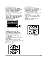
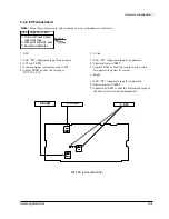
9. R-Y Positive Gain
1) Camera ÒE-EÓ, 3100¡K color bar chart.
2) Video(output) jack and register of EEPROM.
3) Connect video(output) jack to waveform monitor
input jack and monitor TV jack respectively.
4) Press the ÒMENU (MODE UP)/DATE
(MODE DOWN)Ó button so that the OSD state is
Ò32 CRGP XX XXÓ.
5) Aim the camera at a color bar chart illuminated at
1500 to 2000 lx.
6) Adjust the Ò DISPLAY (DATA UP)/C.RESET(DATA
DOWN)Ó button so that the red level is 70IRE.
7) Be sure to press the ÒTITLE (CONFIRM)Ó
button to memorize setting.
8) The OSD shows ÒOK!Ó.
70IRE
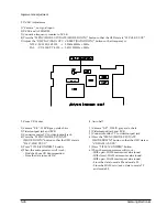
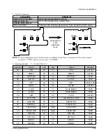
8. Pre white balance (II)
1) Camera ÒE-EÓ, 3100¡K gray-scale chart.
2) Video(output) jack and AF MICOM.
4) Connect vectorscope input jack to video(output)
jack.
3) Press the ÒMENU (MODE UP)/DATE
(MODE DOWN)Ó button so that the OSD state is
Ò1D CWBB XX XXÓ.
5) Aim the camera at a 3100¡K gray-scale chart
illuminated at 1500 to 2000 lx.
6) Adjust the Ò DISPLAY (DATA UP)/ C.RESET
(DATA DOWN)Ó button so that the white vector
moves to the R-Y axial on screen of the vectorscope.
7) The OSD shows ÒOK!Ó.
Match the white luminance
point with the
black luminance
point
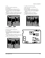
10. R-Y Negative Gain
1) Camera ÒE-EÓ, 3100¡K color bar chart.
2) Video(output) jack and register of EEPROM.
3) Connect video(output) jack to waveform monitor
input jack and monitor TV jack respectively.
4) Press the ÒMENU (MODE UP)/DATE
(MODE DOWN)Ó button so that the OSD state is
Ò33 CRGN XX XXÓ.
5) Aim the camera at a color bar chart illuminated at
1500 to 2000 lx.
6) Adjust the Ò DISPLAY (DATA UP) /C.RESET(DATA
DOWN)Ó button so that the cyan level is 65IRE.
7) Be sure to press the ÒTITLE (CONFIRM)Ó
button to memorize setting.
8) The OSD shows ÒOK!Ó.
65IRE
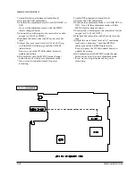
11. B-Y Positive Gain
1) Camera ÒE-EÓ, 3100¡K color bar chart.
2) Video(output) jack and register of EEPROM.
3) Connect video(output) jack to waveform monitor
input jack and monitor TV jack respectively.
4) Press the ÒMENU (MODE UP)/DATE
(MODE DOWN)Ó button so that the OSD state is
Ò36 CBGP XX XXÓ.
5) Aim the camera at a color bar chart illuminated at
1500 to 2000 lx.
6) Adjust the Ò DISPLAY (DATA UP)/C.RESET
(DATA DOWN)Ó button so that the blue level is
50IRE.
7) Be sure to press the ÒTITLE (CONFIRM)Ó
button to memorize setting.
8) The OSD shows ÒOK!Ó.
50IRE
Summary of Contents for VP-L100
Page 7: ...Product Specifications 3 4 Samsung Electronics MEMO ...
Page 21: ...Disassembly and Reassembly 4 14 Samsung Electronics MEMO ...
Page 67: ...Exploded View and Parts List 6 2 Samsung Electronics 6 1 Cabinet Assembly 1 ...
Page 69: ...Exploded View and Parts List 6 4 Samsung Electronics 6 2 Cabinet Assembly 2 ...
Page 77: ...Exploded View and Parts List 6 12 Samsung Electronics 6 6 EVF ...
Page 79: ...Exploded View and Parts List 6 14 Samsung Electronics MEMO ...
Page 105: ...Block Diagrams 8 2 Samsung Electronics 8 1 Overall Block Diagram Camera ...
Page 106: ...Block Diagrams Samsung Electronics 8 3 8 2 Overall Block Diagram VCR ...
Page 107: ...Block Diagrams 8 4 Samsung Electronics 8 3 DC DC Converter ...
Page 108: ...Block Diagrams Samsung Electronics 8 5 8 4 Drum Servo ...
Page 109: ...Block Diagrams 8 6 Samsung Electronics 8 5 Capstan Servo ...
Page 110: ...Block Diagrams Samsung Electronics 8 7 8 6 Video Playback SCL100 150 ...
Page 111: ...Block Diagrams 8 8 Samsung Electronics 8 7 Video Record SCL100 150 ...
Page 112: ...Block Diagrams Samsung Electronics 8 9 8 8 Video Playback VP L100 150 ...
Page 113: ...Block Diagrams 8 10 Samsung Electronics 8 9 Video Record VP L100 150 ...
Page 114: ...Block Diagrams Samsung Electronics 8 11 8 10 Audio ...
Page 115: ...Block Diagrams 8 12 Samsung Electronics 8 11 Camera Main ...
Page 117: ...PCB Diagrams 9 2 Samsung Electronics 9 1 Main Component Side ...
Page 118: ...PCB Diagrams Samsung Electronics 9 3 Conductor Side ...
Page 119: ...PCB Diagrams 9 4 Samsung Electronics 9 2 Rear Component Side Conductor Side ...
Page 120: ...PCB Diagrams Samsung Electronics 9 5 9 3 Function AE 9 4 Function VCR ...
Page 121: ...PCB Diagrams 9 6 Samsung Electronics 9 5 Function Menu ...
Page 123: ...PCB Diagrams 9 8 Samsung Electronics 9 7 CCD Component Side Conductor Side ...
Page 124: ...PCB Diagrams Samsung Electronics 9 9 9 8 LCD Component Side ...
Page 125: ...PCB Diagrams 9 10 Samsung Electronics Conductor Side ...
Page 126: ...PCB Diagrams Samsung Electronics 9 11 Component Side 9 1 MAIN BLUE ...
Page 127: ...PCB Diagrams 9 12 Samsung Electronics Conductor Side 9 1 MAIN BLUE ...
Page 128: ...Samsung Electronics 10 1 10 Wiring Diagram ...
Page 131: ...Schematic Diagrams Samsung Electronics 11 3 11 1 DC DC Converter ...
Page 132: ...Schematic Diagrams 11 4 Samsung Electronics T T T T T T 1 2 3 4 5 6 11 2 System Control Servo ...
Page 133: ...Schematic Diagrams Samsung Electronics 11 5 1 2 3 4 5 6 7 8 11 3 Video ...
Page 134: ...Schematic Diagrams 11 6 Samsung Electronics 11 4 Audio ...
Page 135: ...Schematic Diagrams Samsung Electronics 11 7 11 5 Front ...
Page 136: ...Schematic Diagrams 11 8 Samsung Electronics 11 6 Function AE ...
Page 137: ...Schematic Diagrams Samsung Electronics 11 9 11 7 Function VCR ...
Page 138: ...Schematic Diagrams 11 10 Samsung Electronics 11 8 Function MENU ...
Page 139: ...Schematic Diagrams Samsung Electronics 11 11 11 9 Rear ...
Page 140: ...Schematic Diagrams 11 12 Samsung Electronics 11 10 LCD ...
Page 141: ...Schematic Diagrams Samsung Electronics 11 13 11 11 CCD 1 2 3 4 5 6 7 8 ...
Page 142: ...Schematic Diagrams 11 14 Samsung Electronics 11 12 Camera Main 3 2 1 6 7 4 5 8 ...
Page 143: ...Schematic Diagrams Samsung Electronics 11 15 11 13 EVF ...
Page 144: ...Schematic Diagrams 11 16 Samsung Electronics 11 14 Adaptor ...


