Alignment and adjustment
5-42
Samsung Electronics
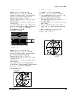
7. Audio Deviation adjustment (Audio Block)
1) Get into the VCR adjustment.
2) Confirm the adjustment mode is 6:AUDIO DEV. in
OSD.
If not, fit the adjustment mode with the MENU
(mode change) button.
3) Connect the oscilloscope to the camcorderÕs audio
output (or Pin #8 of CN502)
4) Playback the camcorder with SP mode color bar
tape.
5) Adjust the wave formÕs level to be 1.0V±0.1Vp-p
with the DISPLAY(data-up) and the C.RESET
(data-down).
Be sure to press the TITLE(confirm) button to
update the setting.
6) If completed, press the MENU(mode change)
button to move to the next adjustment mode.
*. If you want to stop adjustment, do power
resourcing.
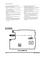
Test point
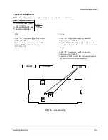
8. Audio BPF adjustment (Audio Block)
1) Get into the VCR adjustment.
2) Confirm the adjustment mode is 7:AUDIO BPF. in
OSD. If not, fit the adjustment mode with the
MENU (mode change) button.
3) Connect the oscilloscope to the camcorderÕs audio
output (or Pin #8 of CN502).
4) Playback the camcorder with SP mode color bar
tape.
5) Adjust the wave formÕs level to be Òmaximum
level and no distortionÓ with the DISPLAY
(data-up) and the C.RESET(data-down).
Be sure to press the TITLE(confirm) button to
update the setting.
6) If completed, press the MENU(mode change)
button to move to the next adjustment mode.
*. If you want to stop adjustment, do power
resourcing.
Summary of Contents for VP-L100
Page 7: ...Product Specifications 3 4 Samsung Electronics MEMO ...
Page 21: ...Disassembly and Reassembly 4 14 Samsung Electronics MEMO ...
Page 67: ...Exploded View and Parts List 6 2 Samsung Electronics 6 1 Cabinet Assembly 1 ...
Page 69: ...Exploded View and Parts List 6 4 Samsung Electronics 6 2 Cabinet Assembly 2 ...
Page 77: ...Exploded View and Parts List 6 12 Samsung Electronics 6 6 EVF ...
Page 79: ...Exploded View and Parts List 6 14 Samsung Electronics MEMO ...
Page 105: ...Block Diagrams 8 2 Samsung Electronics 8 1 Overall Block Diagram Camera ...
Page 106: ...Block Diagrams Samsung Electronics 8 3 8 2 Overall Block Diagram VCR ...
Page 107: ...Block Diagrams 8 4 Samsung Electronics 8 3 DC DC Converter ...
Page 108: ...Block Diagrams Samsung Electronics 8 5 8 4 Drum Servo ...
Page 109: ...Block Diagrams 8 6 Samsung Electronics 8 5 Capstan Servo ...
Page 110: ...Block Diagrams Samsung Electronics 8 7 8 6 Video Playback SCL100 150 ...
Page 111: ...Block Diagrams 8 8 Samsung Electronics 8 7 Video Record SCL100 150 ...
Page 112: ...Block Diagrams Samsung Electronics 8 9 8 8 Video Playback VP L100 150 ...
Page 113: ...Block Diagrams 8 10 Samsung Electronics 8 9 Video Record VP L100 150 ...
Page 114: ...Block Diagrams Samsung Electronics 8 11 8 10 Audio ...
Page 115: ...Block Diagrams 8 12 Samsung Electronics 8 11 Camera Main ...
Page 117: ...PCB Diagrams 9 2 Samsung Electronics 9 1 Main Component Side ...
Page 118: ...PCB Diagrams Samsung Electronics 9 3 Conductor Side ...
Page 119: ...PCB Diagrams 9 4 Samsung Electronics 9 2 Rear Component Side Conductor Side ...
Page 120: ...PCB Diagrams Samsung Electronics 9 5 9 3 Function AE 9 4 Function VCR ...
Page 121: ...PCB Diagrams 9 6 Samsung Electronics 9 5 Function Menu ...
Page 123: ...PCB Diagrams 9 8 Samsung Electronics 9 7 CCD Component Side Conductor Side ...
Page 124: ...PCB Diagrams Samsung Electronics 9 9 9 8 LCD Component Side ...
Page 125: ...PCB Diagrams 9 10 Samsung Electronics Conductor Side ...
Page 126: ...PCB Diagrams Samsung Electronics 9 11 Component Side 9 1 MAIN BLUE ...
Page 127: ...PCB Diagrams 9 12 Samsung Electronics Conductor Side 9 1 MAIN BLUE ...
Page 128: ...Samsung Electronics 10 1 10 Wiring Diagram ...
Page 131: ...Schematic Diagrams Samsung Electronics 11 3 11 1 DC DC Converter ...
Page 132: ...Schematic Diagrams 11 4 Samsung Electronics T T T T T T 1 2 3 4 5 6 11 2 System Control Servo ...
Page 133: ...Schematic Diagrams Samsung Electronics 11 5 1 2 3 4 5 6 7 8 11 3 Video ...
Page 134: ...Schematic Diagrams 11 6 Samsung Electronics 11 4 Audio ...
Page 135: ...Schematic Diagrams Samsung Electronics 11 7 11 5 Front ...
Page 136: ...Schematic Diagrams 11 8 Samsung Electronics 11 6 Function AE ...
Page 137: ...Schematic Diagrams Samsung Electronics 11 9 11 7 Function VCR ...
Page 138: ...Schematic Diagrams 11 10 Samsung Electronics 11 8 Function MENU ...
Page 139: ...Schematic Diagrams Samsung Electronics 11 11 11 9 Rear ...
Page 140: ...Schematic Diagrams 11 12 Samsung Electronics 11 10 LCD ...
Page 141: ...Schematic Diagrams Samsung Electronics 11 13 11 11 CCD 1 2 3 4 5 6 7 8 ...
Page 142: ...Schematic Diagrams 11 14 Samsung Electronics 11 12 Camera Main 3 2 1 6 7 4 5 8 ...
Page 143: ...Schematic Diagrams Samsung Electronics 11 15 11 13 EVF ...
Page 144: ...Schematic Diagrams 11 16 Samsung Electronics 11 14 Adaptor ...


