background image

VIDEO CASSETTE RECORDER

Chassis : Scorpio
VR9180/9160/8160/5160
VR9180C/9160C/VR8170C/VR8160C/VR8140C
VR5160C/5140C

SERVICE 

1. Precautions

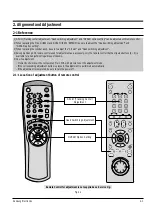
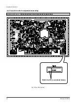
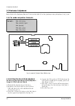
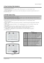
2. Alignment and Adjustment

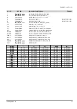
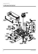
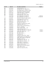
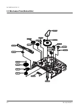
3. Exploded View and Parts List

4. Electrical Parts List

5. Schematic Diagrams

Manual 

VIDEO CASSETTE RECORDER

CONTENTS

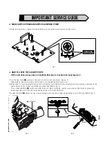
For mechanical disassembly and adjustment, refer to the “Mechanical Manual” (TS-10       AC68-01405A).
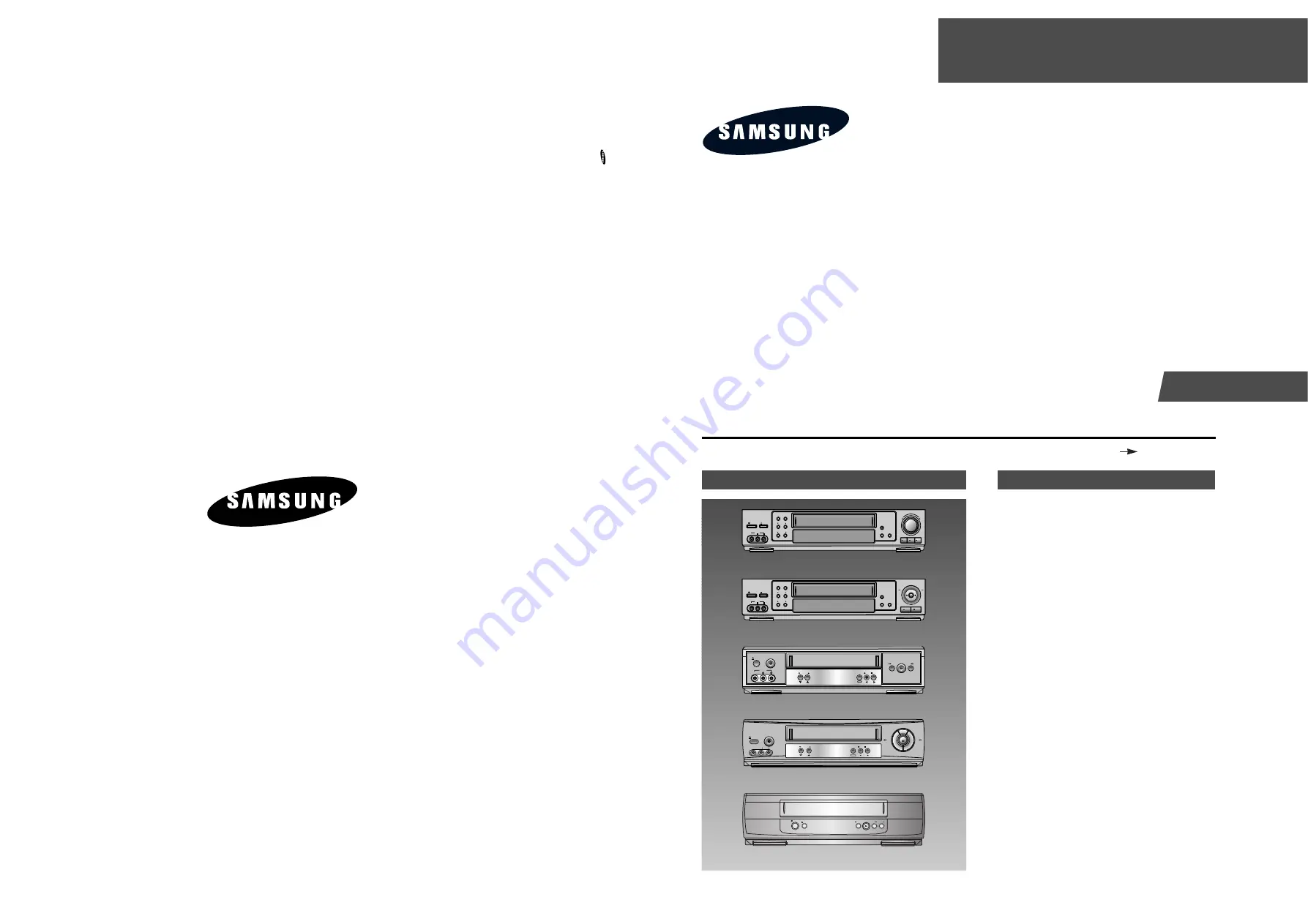
VIDEO           L   AUDIO   R

LINE IN

POWER                     EJECT

TV/VCR        MENU

CHANNEL

TRACKING

REC

INPUT      TAPE SPEED

PLAY               P/S                STOP

JOG/

SHUTTLE

VIDEO           L   AUDIO   R

LINE IN

POWER                     EJECT

TV/VCR        MENU

CHANNEL

TRACKING

REC

INPUT      TAPE SPEED

P/S                            STOP

REW

F.F

VR9180/9180C

VR9160/9160C

EJECT

POWER

VIDEO             L   AUDIO   R

LINE IN 2

CHANNEL

REC         STOP

MENU

PLAY

REW

F.F

VR8160/5160/8160C/5160C

VR8170C

VR8140C/5140C

POWER

EJECT

POWER                                                                REC

REW

PLAY

F.F

STOP

EJECT

POWER

CHANNEL

REC        STOP

MENU

REW

PLAY

F.F

LINE IN 2

VIDEO             L   AUDIO    R

SERVICE MANUAL

VR9180/9160/9180C/9160C/5160/5160C

ELECTRONICS

© Samsung Electronics Co., Ltd. 

FEB. 2001

Printed in Korea

AC68-01467A

Summary of Contents for VR5140C

Page 1: ...R LINE IN POWER EJECT TV VCR MENU CHANNEL TRACKING REC INPUT TAPE SPEED PLAY P S STOP JOG SHUTTLE VIDEO L AUDIO R LINE IN POWER EJECT TV VCR MENU CHANNEL TRACKING REC INPUT TAPE SPEED P S STOP REW F F VR9180 9180C VR9160 9160C EJECT POWER VIDEO L AUDIO R LINE IN 2 CHANNEL REC STOP MENU PLAY REW F F VR8160 5160 8160C 5160C VR8170C VR8140C 5140C POWER EJECT POWER REC REW PLAY F F STOP EJECT POWER CH...

Page 2: ...e screw of Motor Load Ass y Separate the Motor Load Ass y 2 When Slider S T are approached in the position of unloading rotate holder Clutch counterclockwise after inserting screw driver in the hole of frame s bottom in order to wind the unwiunded tape Refer to Fig 3 If you rotate Gear Worm Πcontinuously when tape is in state of unwinding you may cause a tape contamination by grease and tape dama...

Page 3: ...ot exceed 0 5 milliamp Reverse the power plug prongs in the AC outlet and repeat the test 6 X ray Limits The picture tube is designed to prohibit X ray emissions To ensure continued X ray protection replace the picture tube only with one that is the same type as the original Fig 1 1 AC Leakage Test 7 Antenna Cold Check With the unit s AC plug disconnected from the AC source connect an electrical j...

Page 4: ... instrument s ground lead to the instrument chassis ground before connecting the positive lead always remove the instrument s ground lead last 17 Observe the original lead dress especially near the following areas Antenna wiring sharp edges and especially the AC and high voltage power supplies Always inspect for pinched out of place or frayed wiring Do not change the spacing between components and...

Page 5: ...justment Momently short circuit the test point on Main PCB with pincers to set the adjustment mode If the corresponding adjustment button is pressed the adjustment is performed automatically If the adjustment is completed be sure to turn the power off 2 1 1 Location of adjustment button of remote control Fig 2 1 SHUTTLE V LOCK REPLAY F ADV SKIP TV VCR PREV CH REC REC SPEED LINE IN AUDIO SEARCH EXI...

Page 6: ...Adjustment Samsung Electronics 2 1 2 Test point location for adjustment mode setting Fig 2 2 Main PCB Top View Short Circuit for a second and release Application Models VR9180 9160 9180C 9160C 8160 5160 8170C 8160C 5160C ...

Page 7: ...Alignment and Adjustment 2 3 Samsung Electronics Fig 2 3 Main PCB Top View Short Circuit for a second and release Application Models VR8140C 5140C ...

Page 8: ... 2 2 2 ACE Head Position X Point Adjustment See the 2 2 1 d ACE Head Position X Point Adjustment on page 2 2 of the Mechanical Manual 1 Playback the alignment tape Color bar 2 Momently short circuit the test point on Main PCB with pincers to set the adjustment mode See Fig 2 2 and 2 3 3 Press the 5 button of remote control then adjust ment is operated automatically See Fig 2 1 4 Connect the CH 1 p...

Page 9: ...ontrol again to store the option number COMPLETE is displayed for a second as shown Fig 2 6 and the setting is completed 6 Turn the Power off 1 NVRAM Option is adjusted at production line basically 2 In case Micom IC601 and NVRAM IC603 EEPROM is replaced be sure to set the corresponding option number of the repaired model If the option is not set the unit is not operated MOVE SAVE MENU 01 02 03 04...

Page 10: ...2 6 Alignment and Adjustment Samsung Electronics MEMO ...

Page 11: ...Samsung Electronics 3 1 3 Exploded View and Parts List 3 1 Cabinet Assembly 3 2 Mechanical Parts Top Side 3 3 Mechanical Parts Bottom Side Page 3 2 3 4 3 6 ...

Page 12: ...60C 5160C VR9160 9160C REMOTE CONTROL VR9180 9180C VR9160 8160 5160 9160C 8170C 8160C 5160C VR8410C 5410C SHUTTLE V LOCK REPLAY F ADV SKIP TV VCR PREV CH REC REC SPEED LINEIN AUDIO SEARCH EXIT CLEAR DISPLA Y POWER EJECT CH TRK VCR TV A TRK ENTER MENU SLOW VOL 100 VCR POWER TV POWER EJECT TV VCR SLOW A TRK 100 TV VCR TRACKING SELECT AUDIO VOL CH PREV CH DISPLAY SEARCH EXIT REC P STILL MENU REC SPEE...

Page 13: ...LK X 9 S601A AC61 21008A HOLDER SENSOR POM M90 44 BLK X 9 S602A AC61 21008A HOLDER SENSOR POM M90 44 BLK X 9 TM401B Refer to table below CONNECTOR BOARD ASSY HIPS T2 61 BL UT01 Refer to table below REMOCON ASSY MODELS 1 21 101 TM401B UT01 VR9180 AC97 01273B AC64 00606C AC64 00124D AC61 00058A AC59 00025C VR9160 AC97 01273A AC64 00606A AC64 00124D AC61 00058A AC59 00024D VR8160 AC97 01287A AC64 006...

Page 14: ...g Electronics 3 2 Mechanical Parts Top Side G001 G555 G510 G480 K546 G680 G681 B410 B575 B440 B448 B452 G546 G060 G520 G527 K188 K182 K110 K240 K248 K350 K330 K140 K340 G070 K470 B474 B473 K250 K530 K490 G530 G420 G450 K502 OPTIONAL OPTIONAL ...

Page 15: ...H M2 6 L5 0 ZPC G520 AC66 00033A LEVER 9 GUIDE ASS Y TS 10 G527 AC61 60553A SPRING 9 GUIDE ES SUS304 WPB OD3 1 0 G530 AC33 00007A HEAD FE HVFHPOO43A G546 AC66 00005A LEVER FL DOOR TS 10 POM NAT G555 AC66 00032A LEVER UNIT PINCH ASS Y TS 10 G680 AC66 00046A LEVER HEAD CLEANER ASS Y TS 10 POM URETH OPTIONAL G681 AC61 50686A SLEEVE HEAD CLEANER POM TS OPTIONAL K110 AC66 10267A REEL DISK S X 9 POM K14...

Page 16: ...Exploded View and Parts List 3 6 Samsung Electronics 3 3 Mechanical Parts Bottom Side G542 B462 B560 B501 B484 B488 B500 B456 B458 B464 B468 K222 K200 K225 K221 B478 B570 B460 B489 ...

Page 17: ... 00016A LEVER TENSION DRIVE TS 10 SECC E20 20 1 B484 AC66 00030A GEAR LOADING DR ASS Y TS 10 POM SWPB B488 AC66 00023A LEVER S LOADING TS 10 POM NAT B489 AC66 00021A LINK LOADING S TS 10 SECC E20 20 0 8 B500 AC66 00024A LEVER T LOADING TS 10 POM NAT B501 AC66 00022A LINK LOADING T TS 10 SECC E20 20 0 8 B560 AC31 00010A MOTOR CAPSTAN SANKYO B570 AC60 10514A SCREW CAPSTAN PH M2 6 L6 G542 AC66 60051A...

Page 18: ...Exploded View and Parts List 3 8 Samsung Electronics MEMO ...

Page 19: ...1 8X3 2M R1SS01 2003 000994 R METAL OXIDE S 33Kohm 5 2W AF TP 3 9x R1SS02 2003 000994 R METAL OXIDE S 33Kohm 5 2W AF TP 3 9x R1SS04 2001 000429 R CARBON 1KOHM 5 1 8W AA TP 1 8X3 2MM R1SS05 2004 000869 R METAL 3Kohm 1 1 8W AA TP 1 8x3 2mm HIFI ONLY R1SS06 2004 000459 R METAL 2 2Kohm 1 1 8W AA TP 1 8x3 2m VA1SS1 1405 001026 VARISTOR 470V 600A 9x7mm TP ZD1SR1 0403 000571 DIODE ZENER UZP43B 43V 40 46V...

Page 20: ...2001 000429 R CARBON 1KOHM 5 1 8W AA TP 1 8X3 2MM R617 2007 000221 R CHIP 1 2KOHM 5 1 10W DA TP 2012 R618 2007 001039 R CHIP 56KOHM 5 1 10W DA TP 2012 R619 2001 000290 R CARBON 10KOHM 5 1 8W AA TP 1 8X3 2MM R620 2001 000290 R CARBON 10KOHM 5 1 8W AA TP 1 8X3 2MM R621 2007 000931 R CHIP 470OHM 5 1 10W DA TP 2012 R622 2007 000931 R CHIP 470OHM 5 1 10W DA TP 2012 R623 2007 000300 R CHIP 10KOHM 5 1 10...

Page 21: ...UCTOR RADIAL 15mH 5 6 2x7 4mm L307 2701 000002 INDUCTOR AXIAL 100uH 10 4 2x9 8mm Q302 0501 000303 TR SMALL SIGNAL KSA733 PNP 250mW TO 92 T Q303 0501 000398 TR SMALL SIGNAL KSC945 NPN 250mW TO 92 T Q304 0501 000303 TR SMALL SIGNAL KSA733 PNP 250mW TO 92 T Q305 0501 000442 TR SMALL SIGNAL KTC3203 Y NPN 400MW T0 9 Q306 0501 000303 TR SMALL SIGNAL KSA733 PNP 250mW TO 92 T Q307 0501 000442 TR SMALL SIG...

Page 22: ...00438 C AL 10uF 20 25V GP 5x11 2mm C8F1 2202 002037 C CERAMIC MLC AXIAL 100nF 80 20 50V Y5V F A V ONLY C8M2 2203 000802 C CERAMIC CHIP 33nF 10 50V X7R TP 2012 MONO ONLY JK801 AC37 20001G JACK RCA DPAE 6P HIFI PI3 3 HIFI ONLY JK801 AC37 20001H JACK RCA DPAM 4P MONO PI3 3 MONO ONLY Q801 0501 000303 TR SMALL SIGNAL KSA733 PNP 250mW TO 92 T R801 2001 000969 R CARBON 75OHM 5 1 8W AA TP 1 8X3 2MM R802 2...

Page 23: ... SWITCH TACT 12V 50mA 16gf 50gf 6x6mm SP SW709 3404 001076 SWITCH TACT 12V 50mA 16gf 50gf 6x6mm SP SW710 3404 001076 SWITCH TACT 12V 50mA 16gf 50gf 6x6mm SP SW711 3404 001076 SWITCH TACT 12V 50mA 16gf 50gf 6x6mm SP SW715 3404 000165 SWITCH TACT 12V 50mA 160gf 6x6mm SPST SW716 3404 000165 SWITCH TACT 12V 50mA 160gf 6x6mm SPST ASSY FUNCTION VR9180 XAA TS 10 SEA J S S N A CN704 3710 001563 CONNECTOR ...

Page 24: ...R 470V 600A 9x7mm TP POWER PARTS C1P101 2401 001730 C AL 10uF 20 50V GP TP 5x11 2 5 C1P103 2401 001254 C AL 4 7uF 20 35V GP TP 4x7 5 C1P104 2401 001254 C AL 4 7uF 20 35V GP TP 4x7 5 C1P105 2401 000598 C AL 1uF 20 50V GP TP 4x7 5 C1P106 2401 000598 C AL 1uF 20 50V GP TP 4x7 5 C1P108 2401 003107 C AL 47uF 20 16V GP TP 5x7 5 C1P109 2401 003107 C AL 47uF 20 16V GP TP 5x7 5 C1P112 2401 001254 C AL 4 7u...

Page 25: ...KOHM 5 1 8W AA TP 1 8X3 2MM R624 2001 000290 R CARBON 10KOHM 5 1 8W AA TP 1 8X3 2MM R630 2001 000864 R CARBON 56KOHM 5 1 8W AA TP 1 8X3 2MM R631 2001 000864 R CARBON 56KOHM 5 1 8W AA TP 1 8X3 2MM R632 2001 000786 R CARBON 47KOHM 5 1 8W AA TP 1 8X3 2MM R633 2007 000565 R CHIP 220KOHM 5 1 10W DA TP 2012 R634 2007 000068 R CHIP 470KOHM 5 1 10W DA TP 2012 R635 2001 000429 R CARBON 1KOHM 5 1 8W AA TP 1...

Page 26: ...TP 2012 R313 2001 000258 R CARBON 1 8KOHM 5 1 8W AA TP 1 8X3 2M R314 2007 000241 R CHIP 1 5KOHM 5 1 10W DA TP 2012 R315 2007 001177 R CHIP 8 2KOHM 5 1 10W DA TP 2012 R316 2007 000300 R CHIP 10KOHM 5 1 10W DA TP 2012 R317 2001 000411 R CARBON 18KOHM 5 1 8W AA TP 1 8X3 2MM R318 2001 000411 R CARBON 18KOHM 5 1 8W AA TP 1 8X3 2MM R319 2001 000290 R CARBON 10KOHM 5 1 8W AA TP 1 8X3 2MM R320 2007 000221...

Page 27: ...W AA TP 2 4X6 4MM R803 2007 001239 R CHIP 910OHM 5 1 10W DA TP 2012 R804 2007 001166 R CHIP 75OHM 5 1 10W DA TP 2012 R8L1 2001 000356 R CARBON 150KOHM 5 1 8W AA TP 1 8X3 2M R8L2 2001 000356 R CARBON 150KOHM 5 1 8W AA TP 1 8X3 2M R8L3 2001 000449 R CARBON 2 2KOHM 5 1 8W AA TP 1 8X3 2M R8L4 2001 000780 R CARBON 470OHM 5 1 8W AA TP 1 8X3 2MM R8L5 2001 000734 R CARBON 4 7KOHM 5 1 8W AA TP 1 8X3 2M R8M...

Page 28: ...4 10 Samsung Electronics Electrical Parts List MEMO ...

Page 29: ...ntification of Main PCB 5 2 5 1 S M P S Power 5 3 5 2 Logic 5 4 5 3 Audio Video 5 6 5 4 Hi Fi Option 5 8 5 5 TM Block Input Output 5 10 5 6 Display LED Module VR9180 9160 8160 5160 9180C 9160C 8170C 8160C 5160C 5 11 5 7 Display LED Lamp VR8140C 5140C 5 12 ...

Page 30: ...atically sensitive ES devices section of this service manual Note Do not use the part number shown on this drawing for ordering The correct part number is shown in the parts list may be slightly different or amended since this drawing was prepared Important safety notices Components identified with the mark have the special characteristics for safety When replacing any of these components Use only...

Page 31: ...Schematic Diagrams Samsung Electronics 5 3 5 1 S M P S Power PWR OFF PWR ON ΠΠQ1SR02 COLLECTOR POWER OFF 240Vp p Q1SR02 COLLECTOR POWER ON 270Vp p ...

Page 32: ...Schematic Diagrams 5 4 Samsung Electronics 5 2 Logic Ø ˆ Œ ˇ ...

Page 33: ...s 5 5 IC601 VOLTAGE TABLE WAVEFORM IC601 MN101D02X Œ IC601 35 PB 3Vp p IC601 37 38 PB REC 620mVp p IC601 34 PB 5Vp p IC601 47 PB REC 2 2Vp p ˇ IC601 33 PB 5Vp p IC601 50 PB REC 1 8Vp p CN604 6 PB 5Vp p ˆ IC602 8 PB 5Vp p Ø TP601 PB 3 2Vp p ...

Page 34: ...Schematic Diagrams 5 6 Samsung Electronics 5 3 Audio Video ˇ ˆ Ø Œ ...

Page 35: ...ics 5 7 IC301 VOLTAGE TABLE WAVEFORM IC301 LA71200M Œ IC301 9 REC 3Vp p IC301 73 REC SP 4Vp p IC301 21 PB REC 440mVp p IC301 10 PB 1 4Vp p ˇ IC301 24 PB REC 250mVp p IC301 39 PB REC 400mVp p ˆ TP301 PB 600mVp p Ø IC301 66 REC EP 3 1Vp p ...

Page 36: ...Schematic Diagrams 5 8 Samsung Electronics 5 4 Hi Fi Option Œ ˇ ...

Page 37: ...Schematic Diagrams Samsung Electronics 5 9 IC501 VOLTAGE TABLE WAVEFORM IC501 AN3662FBP Œ IC501 30 PB 50mVp p IC501 21 PB 50mVp p ˇ IC501 53 57 PB REC 150mVp p ...

Page 38: ...Schematic Diagrams 5 10 Samsung Electronics 5 5 TM Block Input Output ΠTM401 18 REC 100mVp p TM401 20 REC 100mVp p Π...

Page 39: ...Schematic Diagrams Samsung Electronics 5 11 5 6 Display LED Module VR9180 9160 8160 5160 9180C 9160C 8170C 8160C 5160C s ...

Page 40: ...Schematic Diagrams 5 12 Samsung Electronics 5 7 Display LED Lamp VR8140C 5140C ...

Page 41: ...sembly and Reassembly 2 Alignment and Adjustment TS 10 DECK CONTENTS File with the SERVICE MANUAL MECHANICAL MANUAL TS 10 DECK ELECTRONICS Samsung Electronics Co Ltd JUN 2001 Printed in Korea AC68 01451A MECHANICALManual ...

Page 42: ... 1 Œ ˇ ˆ Ø Fig 1 1 Top parts Location 1 Œ GEAR FL CAM MOTOR LOADING ASS Y ˇ LEVER FL ARM ASS Y HOLDER FL CASSETTE ASS Y ˆ LEVER FL DOOR Ø SLIDER FL DRIVE 1 Disassembly and Reassembly 1 1 Deck Parts Locations 1 1 1 Top View ...

Page 43: ... ˇ ˆ Ø Ô Ò Fig 1 2 Top Parts Location 2 Œ FE HEAD CYLINDER ASS Y ˇ ACE HEAD ASS Y LEVER UNIT PINCH ASS Y ˆ LEVER 9 GUIDE ASS Y Ø LEVER TENSION ASS Y BAND BRAKE ASS Y DISK S REEL LEVER S BRAKE ASS Y GEAR IDLE Ô LEVER IDLE LEVER T BRAKE ASS Y Ò DISK T REEL ...

Page 44: ...lectronics 1 3 1 1 2 Bottom View Œ ˇ ˆ Ø Fig 1 3 Bottom Parts Location Œ GEAR JOINT 1 GEAR JOINT 2 ˇ BRACKET GEAR MOTOR CAPSTAN ASS Y ˆ LEVER T LOAD ASS Y Ø GEAR LOADING DRIVE LEVER S LOAD ASS Y HOLDER CLUTCH ASS Y BELT PULLEY SLIDER CAM ...

Page 45: ... y Πas grasping the Holder FL Cassette Ass y Πand Lever FL Cassette R in the same time to release hooking from Main Base until the Boss A of Holder FL Cassette Ass y Πis taken out from the Rail B 3 Lift the Holder FL Cassette Ass y Πin this time you have to grasp the Lever FL Cassette R Continuously until the Holder FL Cassette Ass y Πis taken out completely Note Be sure to insert Lever FL Ca...

Page 46: ...2 3 Slider FL Drive Gear FL Cam Removal 1 Pull the Slider FL Drive Πto the front direction 2 Remove the Slider FL Drive Πin the direction of arrow Refer to Fig 1 6 3 Remove the Gear FL cam Note When reinstalling be sure to reassemble Slider FL drive Πafter you insert the Boss of Lever FL ARM R in Groove of Slider Fl drive ΠAssembly Align the Gear FL Cam Πwith the Gear worm wheel Post as shown...

Page 47: ... Gear Worm Wheel Removal 1 Remove the Gear Worm wheel ΠΠGEAR WORM WHEEL Fig 1 9 Gear Worm Wheel Removal 1 2 6 Motor Loading Ass y Removal 1 Remove the screw Π2 Remove the Motor Loading Ass y MOTOR LOADING ASS Y ΠSCREW Fig 1 10 Motor Loading Ass y Removal ...

Page 48: ... GEAR JOINT 2 1 2 8 Gear Loading Drive Slider Cam Lever Load S T Ass y Removal 1 Remove the Belt Pulley Refer to Fig 1 30 2 Remove the Gear Loading Drive Œ after releasing Hook A in the direction arrow as shown in detail drawing 3 Remove the Slider Cam 4 Remove the Lever Load ˇ Link Load ˆ Lever Load Link Load Ø Œ GEAR LOADING DRIVE ˆ LINK LOAD S ˇ LEVER LOAD S LEVER LOAD T Ø LINK LOAD T SLIDE CAM...

Page 49: ...t of Gear Loading Drive Refer to Timing Point 2 4 Aline dot of Gear Loading drive with mark of Slider Cam ˇ as shown in drawing Refer to Timing Point 3 LEVER LOAD S Œ LEVER LOAD T LEVER LOAD S LEVER LOAD T PIN A PIN C PIN B PIN D ˇ SLIDER CAM TIMING POINT 2 TIMING POINT 1 TIMING POINT 3 1 2 10 Lever Pinch Drive Lever Tension Drive Removal 1 Remove the Lever Pinch Drive Œ Lever Tension Drive Œ LEVE...

Page 50: ...n Ass y seated Rotate stopper of Main Base to the Mark B Œ SPRING TENTION LEVER STOPPER MARK B A LEVER TENTION ASS Y ˇ BAND BRAKE ASS Y 1 2 12 Lever Brake S T Ass y Removal 1 Release the Hook A and the Hook B C in the direction of arrow as shown in Fig 1 17 2 Lift the Lever S T Brake Ass y Œ with spring brake ˇ Assembly 1 Assembly the Lever S Brake Ass y Œ on the Main Base 2 Assembly the Lever T B...

Page 51: ...in the direction of arrow A B 2 Lift the Lever Idle ΠAssembly 1 Apply oil in two Bosses of Lever Idle Π2 Assemble the Gear Idle with the Lever Idle ΠNote When replacing the Gear Idle be sure to add oil in the boss of Lever Idle Π1 2 14 Disk S T Reel Removal 1 Lift the Disk S T Reel ΠGEAR IDLE GEAR IDLE ΠLEVER IDLE A HOOK C B Fig 1 18 Gear Idle Ass y Removal ...

Page 52: ...ion of arrow as shown Fig 1 21 and lift the Lever Up Down Ass y Π2 Lift the Gear Center Ass y Assembly 1 Insert the Lever Up Down Ass y Πin the rectan gular holes on Main Base as shown in Fig 1 22 2 Lift the Lever Up Down Ass y Πabout 35 Refer to Fig 1 22 3 Insert Ring of the Gear Center Ass y in the Guide of the Lever Up Down Ass y Π4 Insert the Gear Center Ass y in the post on Main Base 5 Pu...

Page 53: ...e extreme care not to touch the grease on the Roller Pinch 2 When reinstalling be sure to apply grease on the post pinch roller ˇ SPRING PINCH DRIVE Œ LEVER UNIT PINCH ASS Y PLATE JOINT Fig 1 23 Guide Cassette Door Removal Fig 1 24 Lever Unit Pinch Ass y Plate Joint Spring Pinch Drive Removal 1 2 17 Guide Cassette Door Removal 1 Lift the Hook A 2 Rotate the Guide Cassette Door Œ in the direction o...

Page 54: ...e direction of arrow A Note 1 Take extreme care not to get grease on the tape Guide Post 2 After reinstalling check the bottom side of the Post 9 Guide to the top side of Main Base ΠSPRING 9 GUIDE LEVER 9 GUIDE ASS Y A B Fig 1 25 Lever 9 Guide Ass y Removal 1 2 20 FE Head Removal 1 Remove the screw Π2 Lift the FE Head ΠFE HEAD Fig 1 26 FE Head Removal ...

Page 55: ...connector of ACE Head Ass y 2 Remove the screw Π3 Lift the ACE Head Ass y ΠSCREW HEAD ACE ASS Y 1 2 22 Slider S T Ass y Removal 1 Move the Slider S T Ass y Πto slot and then lift it to remove Refer to arrow ΠSLIDER S ASS Y SLIDER T ASS Y Fig 1 27 ACE Head Removal Fig 1 28 Slider S T Ass y Removal ...

Page 56: ... Œ Note 1 Take care not to touch the Cylinder Ass y ˇ and the tape guide post at reinstalling 2 When reinstalling Don t push down too much on Screw Driver Œ 3 SCREWS PLATE GROUND DECK ˇ CYLINDER ASS Y Fig 1 29 Plate Ground Deck Cylinder Ass y Removal 1 2 24 Belt Pulley Removal 1 Remove the Belt Pulley Œ Note Take extreme care not to get grease on Belt Pulley Œ at assembling or reassembling Œ BELT ...

Page 57: ... DAMPER CAPSTAN ˇ MOTOR CAPSTAN ASS Y 1 2 27 How to Eject the Cassette Tape If the unit does not operate on condition that is inserted into housing ass y 1 Turn the Gear worm Œ clockwise with screw driver Refer to arrow Other method Remove the Screw of Motor Load Ass y Separate the Motor Load Ass y Œ GEAR WORM Fig 1 32 Damper Capstan Motor Capstan Ass y Removal Fig 1 33 2 When Slider S T are appro...

Page 58: ... 8 GUIDE SHAFT CAPSTAN SHAFT 9 GUIDE POST 3 GUIDE POST GUIDE ROLLER S T O O O O O O O CYLINDER ASS Y O O O O O O O O O FE HEAD O O O O O O O ACE HEAD O O O O O O O O O PINCH ROLLER O O O O O O O O O POST REEL S T SLEEVE TENSION POST CENTER LEVER IDLE BOSS 2Point CAPSTAN MOTOR PULLEY O O O O O BELT PULLEY O O O O O O O HOLDER CLUTCH ASS Y O O O O O O O O O GEAR CENTER ASS Y O O O O O O O O O GEAR I...

Page 59: ...1 18 Samsung Electronics Disassembly and Reassembly MEMO ...

Page 60: ...LER GUIDE ROLLER S GUIDE ROLLER T 8 GUIDE POST 9 GUIDE POST CAPSTAN SHAFT ACE HEAD 3 GUIDE POST 2 Alignment and Adjustment 2 1 Tape Transport System and Adjustment Locations The tape transport system has been adjusted precisely in the factory Alignment is not necessary except for the following 1 Noise observed on the screen 2 Tape damage 3 Parts replacement in the tape transport system Lower flang...

Page 61: ... turn the screw A tilt adjust on the ACE head ass y 4 Reconfirm the ACE head height Fig 2 5 Tape Guide Check 2 2 1 c AUDIO AZIMUTH ADJUSTMENT 1 Load alignment tape Mono scope and playback the NTSC 7KHz PAL 6KHz signal 2 Connect channel 1 scope probe to audio output test point 3 Adjust screw B to achieve maximum audio level See Fig 2 3 2 2 1 d ACE HEAD POSITION X POINT ADJUSTMENT 1 See 2 Alignment ...

Page 62: ...t of the video RF envelope at the exit side 4 If the section A in Fig 2 7 does not meet the speci fication adjust the guide roller S up or down 5 If the section B in Fig 2 7 does not meet the speci fication adjust the guide roller T up or down Fig 2 6 Envelope Waveform Adjustment a a b c d c b d a 63 b c d Fig 2 7 Adjustment Points A B A B H D SWITCHING PULSE ENVELOPE 6 Play back the Mono Scope al...

Page 63: ...he unit using with T 120 E 120 The video envelope should meet the specification as shown in Fig 2 10 In SP mode A should equal B If the head gap is wide upper cylinder should be checked A B Fig 2 10 Envelope Output and Output Level 2 2 5 Tape Wrinkle Check 1 Run the T 160 E 180 tape in the playback FPS RPS and Pause modes and observe tape wrinkle at each guide 2 If excessive tape wrinkle is observ...

Reviews: