29
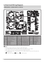
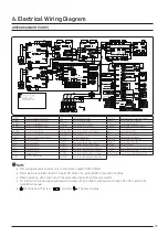
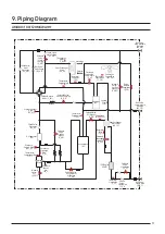
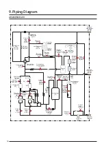
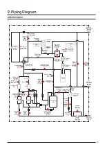
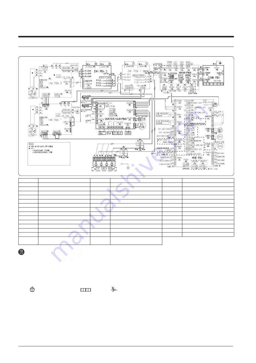
INV PBA1
Printed circuit board(Inverter PBA1)
EEV1
Electrical Expansion Valve 1
LIQUID(10K)
Temp. Sensor (Liquid Tube Temp._10Kohm)
INV PBA2
Printed circuit board(Inverter PBA2)
EEV2
Electrical Expansion Valve 2
HOTGAS1 V/V
Solenoid Valve (Hot Gas Bypass1)
EMI PBA1
Printed circuit board(Noise Filter1)
EVI-OUT(10K)
Temp. Sensor (EVI-out_10kohm)
EVI BYPASS V/V Solenoid Valve (EVI Bypass )
EMI PBA2
Printed circuit board(Noise Filter2)
EVI-IN(10K)
Temp. Sensor (EVI-in_10Kohm)
RETURN V/V
Solenoid Valve (Accumulator Oil Return)
WATER HUB PCB Printed circuit board(Water related load control)
SUCTTION1(10K) Temp. Sensor (Suction Temp.1_10Kohm)
4WAY V/V
Solenoid Valve (4Way Valve )
MAIN PBA
Printed circuit board(main)
SUCTTION2(10K) Temp. Sensor (Suction Temp.2_10Kohm)
CCH1
Crank Case Heater(COMP1)
HUB PBA
Printed circuit board(hub)
SNOW SENSOR
SNOW SENSOR
CCH2
Crank Case Heater(COMP2)
COMM PBA
Printed circuit board(Communication)
OIL-COMP1
Oil-Sensor (Compressor1)
MAIN COOLING
Solenoid Valve (Main Cooling)
COMP1
Motor (Compressor1)
OIL-COMP2
Oil-Sensor (Compressor2)
HOTGAS2 V/V
Solenoid Valve (Hot Gas Bypass2)
COMP2
Motor (Compressor2)
OUT(10K)
Temp. Sensor (Ambient Temp._10Kohm)
OD EEV V/V
Solenoid Valve (Outdoor EEV)
FAN1
Motor (Outdoor Fan1)
COND(10K)
Temp. Sensor (Cond Out Temp._10Kohm)
690V/T56A
FUSE(NOISE FILTER)
FAN2
Motor (Outdoor Fan1)
TOP1(200K)
Temp. Sensor (Compressor Top1_200Kohm)
MODE CHANGE Connector (Remote switching cool/heat selector)
EVI V/V 1
Solenoid Valve(EVI 1)
TOP2(200K)
Temp. Sensor (Compressor Top2_200Kohm)
EXT CON
Connector (Output EXT CON)
EVI V/V 2
Solenoid Valve(EVI 2)
DIS1(200K)
Temp. Sensor (Discharge Temp.1_200Kohm)
ERROR/COMP EXT Connector (Output ERROR/COMP EXT CON)
EVI EEV
Enhanced Vapor Injection
Electrical Expansion Valve
DIS2(200K)
Temp. Sensor (Discharge Temp.2_200Kohm)
NOTE
•
This wiring diagram applies only to the water-cooled DVM S Water.
•
Colors BLK: black, RED: red, BLU: blue, WHT: white, YEL: yellow, BRN: brown, SKY: skyblue
•
When operating, don’t short circuit the protection device (High Pressure switch)
•
For connection wiring indoor-outdoor transmission F1-F2, outdoor-outdoor transmission OF1-OF2, refer to the
installation manual.
•
Protective earth (screw) ,
connector,
: The wire quantity
AM300KXWA∗∗ (30HP)
6. Electrical Wiring Diagram

