41
10. Installation
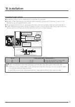
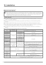
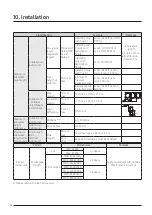
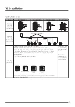
Caution for electrical work
•
You must install ELCB or MCCB + ELB
‐
ELCB: Earth leakage breaker
‐
MCCB: Molded case circuit breaker
‐
ELB: Earth leakage breaker
•
Do not operate the outdoor unit before completing the refrigerant pipe work.
•
Do not disconnect or change the cable inside the product. It may cause damage to the product.
•
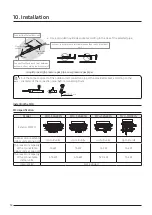
Specification of the power cable is selected based on following installation condition; culvert installation/
ambient temperature 30 °C/ single multi conductor cables. If the condition is different from the ones
stated, please consult an electrical installation expert and re-select the power cable.
‐
If the length of power cable exceed 50m, re-select the power cable considering the voltage drop.
•
Use a power cable made out of incombustible material for the insulator (inner cover) and the sheath (outer
cover).
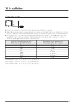
•
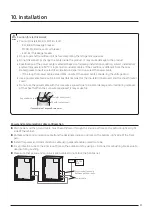
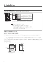
Do not use the power cable with the core wire exposed due to insulator damage occurred during removal
of the sheath. When the core wire is exposed, it may cause fire.
Insulator (inner cover)
Exposed wire core
<The example of exposed core wire>
Sheath (outer cover)
CAUTION
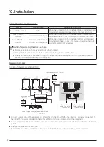
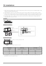
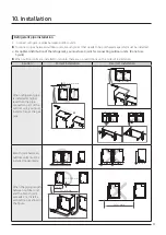
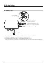
Power and communication cable configuration
▶
Main power and the ground cable must be withdrawn through the knock-out hole on the bottom-right or right
side of the cabinet.
▶
Withdraw the communication cable from the designated knock-out hole on the bottom-right side of the front
part.
▶
Install the power and communication cable using separate cable protection tube.
▶
Fix a protection tube to the knock-out hole on the outdoor unit by using a CD connector or bushing. Make sure to
use insulating bushing.
▶
Make sure that power and communication cables do not block the front panel.
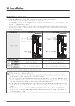
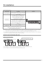
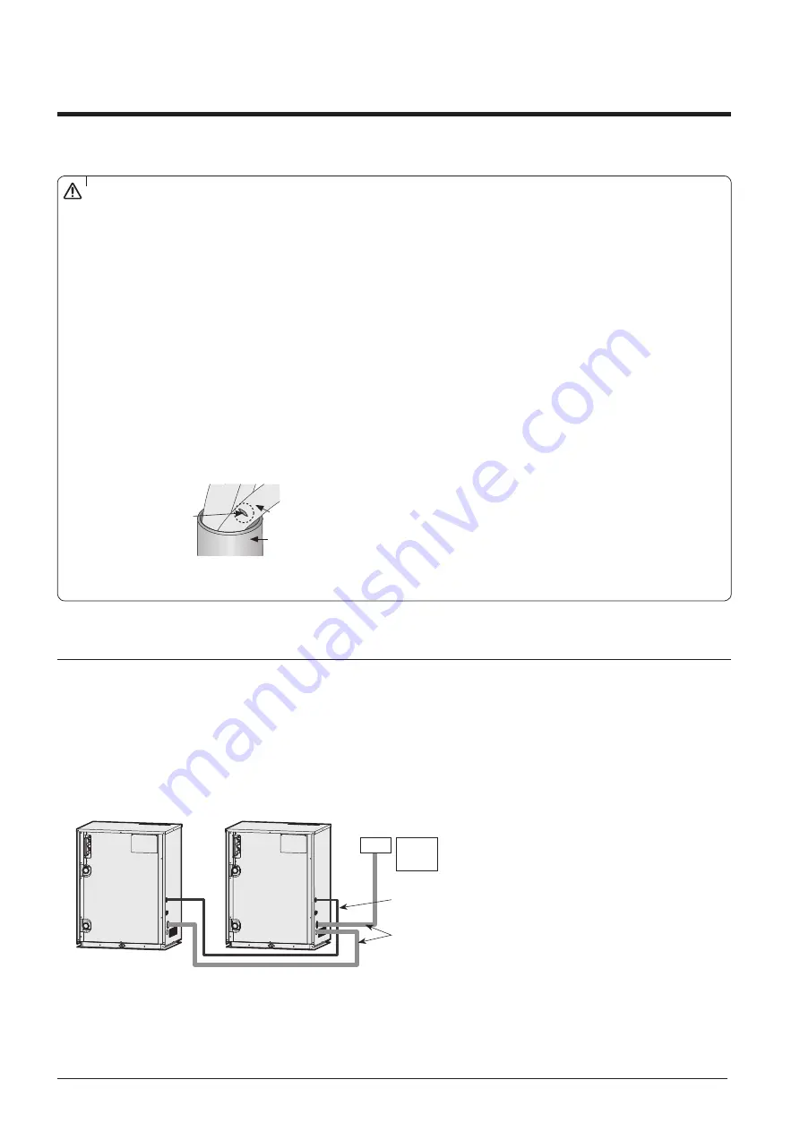
MCCB+
ELB
ELCB
Power cable
Communication cable
between outdoor units
or


