
43
10. Installation
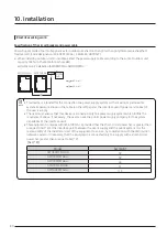
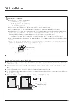
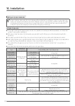
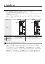
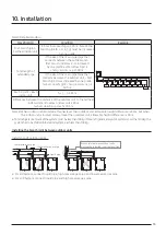
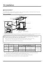
Connecting the power terminal
▶
Connect the cables to the terminal board with solderless ring terminals.
▶
Properly connect the cables by using certified and rated cables and make sure to fix them properly so that
external force is not applied to the terminal.
▶
Use a driver and wrench that can apply the rated torque when tightening the screws on the terminal board.
▶
Tighten the terminal screws by complying rated torque value. If the terminal is loose, fire can occur due to arc
heat generation and if the terminal is too tight, terminal board could get damaged.
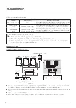
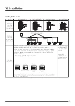
MCCB+
ELB
or
ELCB
3 phase
380-415 V
External power
supply / External
contact signal
Communication cable
(Indoor/Outdoor unit)
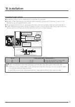
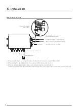
Protection tube for power cable
Conduit
(field supply)
Conduit mounting plate
Lock nut
(field supply)
Sub unit 3 phase
(380-415 V)
(Knock out hole)
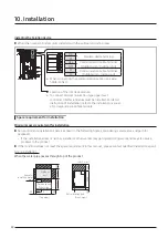
Screw
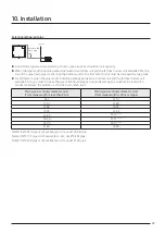
Tightening torque for terminal (N∙m)
M4
1.2~1.8
Single phase (220-240 V) power cable
M8
5.5~7.3
3 phase (380-415 V) power cable
•
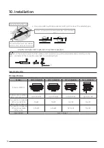
When removing the outer sheath of the power supply cable, be careful not to scratch the inner sheath of the cable.
•
Make sure that more than 20mm of the outer sheath of the indoor unit power and communication cable
are inside the electrical component box.
•
Install the communication cable separately from power cable and other communication cables.
CAUTION


