background image

Troubleshooting _ 27

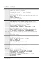
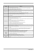
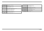
Problem

What To Do

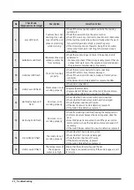
Will Not Lock

•  Perform Quick Test Mode. Check Door Lock.


Check the resistance for door lock. if Approx 0.2 ohm between the terminal of contact (white-Red wire),


 and if not, change PCB(refer to PCB connector check).

• Read Lock Switch and PCB . (Refer to PCB Connector Check.)

Will Not Unlock

•  Flash “HOT LED ”. Turn off and on the unit. If “flashing HOT LED” keeps illuminating, check PCB and Door Lock Switch.
• Read Lock Switch and PCB . (Refer to PCB Connector Check.)
•  Perform Quick Test Mode. Check Door Lock. Check the resistance for door unlock if Approx 0.2 ohm between the 

terminal of contact (white-blue wire), and if not, change PCB(refer to PCB connector check).

No Key Operation

• Option and Function buttons respond differently according to each cycle.
•  Child Lock is being activated. To exit, hold down Spin level key and soil level key simultaneously until it sends out 

a beeping sound.

•  When “End“ illuminates on the display, only Power button works. Press Power button and make new cycle selections.

Will Not Drain

• Check for any kink on the drain hose. If any, straight it out.
• Check for any restriction in the drain hose.
•  Close the door and press the Start/Pause Button. For safety reasons, the washer does not tumble or spin with the 

door open.

• When it is freezing outside, check if it is frozen inside the drain hose.
• Check if the water level signal input is correct. Go to Board Input Test Mode.
• Go to Quick Test Mode and do Drain Pump Test.
• Check if there is any twist in the hose (the one between Tub and Drain Pump).
• Check if it reads AC 120V at the pump when a spin cycle is selected.
• Read the winding resistance of the pump motor. (15±10% Ohms)
•  Check the pump at Pin #3 of CN6 and pin #7 of CN4 on PCB. It should read AC 110~120V. (Refer to PCB Connector Check)

Wrong Water 

Temperature

• Check if both of the water taps are fully open.
•  If the water heater is located far from the washer, screw out the hot water tap and let its water pass until you get 

hot water.

•  Too Hot/Too Cold: Reduced amount of water is supplied while PCB controls the influx to regulate the actual 

temperature of the water in the tub. This may appear to be significantly hotter/colder than expected.

• Check if the temperature selection is correct.
• Disconnect inlet hoses from the Water Valve and remove any residue in the inlet screens.

Noisy and/

or Vibration/

Walking

• Check if the washer is leveled and the lock nuts are tightened up on the bottom plate.
• Check if all of the shipping bolts and spacers are removed from the back panel.
• Check if load is big enough and there is no unbalance. If there is not enough load, put in a few towels to balance it.
• Check if the motor is fastened enough.
• Remove various trouble contributors (such as dust coat on the floor).

Buttons do not 

Respond

• Option and Function buttons respond differently according to each cycle.
•  Child Lock feature has been selected. To disable feature press and hold Temp and Spin simultaneously until a beep 

is heard.

Summary of Contents for WA3000J

Page 1: ...TOP LOADING TYPE BASIC NAME WA3000J BASIC CODE WA40J3000AW A2 MODELNAME WA3000A MODELCODE WA41A3000AW A4 WA40A3005AW A4 1 SafetyInstructions 2 Features and Specifications 3 Disassemblyand Reassembly 4...

Page 2: ...Standard disassembly drawings 10 4 Troubleshooting 18 4 1 Instruction of Function 18 4 2 code Mode Information 20 4 3 Diagnostic Code Corrective Action 21 4 4 Troubleshooting 26 4 5 Q A 28 5 PCB diag...

Page 3: ...ure to disconnect the powerplug before servicing 4 Failing to do so may result in a risk of electric shock Do not allow consumers to connect several appliances to a single poweroutlet at the same time...

Page 4: ...and electric leakage WARNING AFTER SERVICING Check the wiring 4 Ensure that no wire touches a rotating part ora sharpened part of the electrical harness Check foranywaterleakage 4 Perform a test run f...

Page 5: ...e Do not press a control button using a sharp tool orobject 4 This may result in electric shock ordamage to the product CAUTION WHILE SERVICING When wiring a harness make sure to seal it completely so...

Page 6: ...the poweroutlet and measure the insulation resistance between the powerplug and the grounding wire of the washing machine The value must be greaterthan10M when measured with a 500V DC Megger Check whe...

Page 7: ...S 2 1 FEATURES Features Description The Great Capacity Even bulky garments and blankets get superclean The Great capacity leaves enough room fora more thorough cleanerwash EZ Closed Lid The dooris des...

Page 8: ...SHER DIMENSION cm A Height 111 7cm B Width 68 6cm C Height with Dooropen 150 5cm D Depth 74 4cm WATER PRESSURE 20 116psi 137 800kPa WEIGHT 58kg 127 9 lb CAPACITY 4 1 4 0cu ft HEATER RATING WASHING 120...

Page 9: ...Max rpm 700 700 Motor AC Motor AC Motor Design Color Neat White Neat White Centerdisplay No No Jog Dial Squall JrSame Squall JrSame Main display LED LED LED color Red Red DoorLid TC Non glass Non glas...

Page 10: ...CATIONS Item Item Name Code No Remark HOSE HANGER DC61 00224A Default MANUAL BOOK DC68 03520F Default CABLE TIE 6501 000121 Default CAPW V DC61 10449Q Default Note Customercan purchase Watersupply dra...

Page 11: ...Tub 16 Fixerscrew 5 Motor 1 Balance 5 Damper 2 Damper friction1 Double ended spanner 10mm 17mm Replaced by box driver Leg Vice pliers A Tool forprotecting empty turning of bolt or abrasion from using...

Page 12: ...ntrol panel assembly and separate coverpanel 2 Separate the both hooks Left and Right 3 Separate the coverpanel upward If it is difficult to disassemble use the driverto disassemble hooks Be careful d...

Page 13: ...properlyconnected When disassembling and reassembling the housing take care thatyou do not damage the part 8 Pull the PCB s 9 Separate 5 hooks with driver WaterValve 1 Afterseparating the control pane...

Page 14: ...12 _ Disassemblyand Reassembly Part Figure Description DoorAssembly 1 Remove the 4 screws holding the doorlid TC and separate the door...

Page 15: ...rate the watervalve the pressure switch Separate the housing to prevent stress and damage to thewire harness 4 Separate the main wire harness the pressure switch hose clip Grounding screw 5 Remove the...

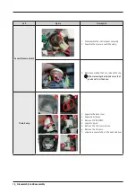
Page 16: ...essure switch housing 3 Before separating the hose release the clip When releasing the clip take care that you do not tearthe hose Drain Pump 1 3 5 2 4 6 1 Separate the back cover 2 Separate 2 clamps...

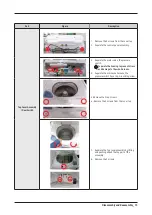
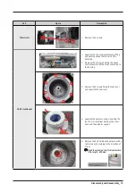
Page 17: ...crews holding the panel control Separate all the wires connected to the housing 3 Remove the 9 screws fixing the tub cover and separate the tub cover 4 Separate the pulsator cap by inserting the tip o...

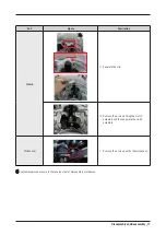
Page 18: ...se direction 7 Place the main body so that the front frame faces upward and remove the 2 bolts holding the saddle with a10mm wrench Whenyou place thewasheron the floor take care thatyou do not damage...

Page 19: ...iption Clutch 11 Separate the clip 12 Remove the 6 screws fixing the clutch assembly and then separate the clutch assembly TMR sensor 1 Remove the 2 screws with a10mm spanner Reassembly procedures are...

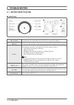
Page 20: ...inkle freeitems Cool Brightlycolored verylightlysoileditems Cold Coldwaterwithnowarmwateradded NOTE IfyouselecttheColdoption allthelampsforthewatertemperatureoptionsareturnedoff ExtraRinse Changefroms...

Page 21: ...gs of heatertemperature etc ATC function in ourwashermaintains the certain level of wash temperature to output the bestwashing performance at each cycle NOTE Ifyou select NORMALcycle this cycle is the...

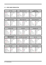
Page 22: ...ode Communication Code Switch Code Main RelayCode WaterLevel Sensor WaterSupplyCode WaterLeakage Code OverflowCode Drain Code Unbalance Code MotorDriving Code TMR SensorCode Mems PBACode Detected Door...

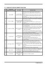
Page 23: ...shes if the main relayconnections are incorrect Check the connections If there is no flashing in the connections replace the main PBA 4 Cool LED flash The WaterLevel sensoris not working properly Chec...

Page 24: ...rol circuit is defective replace the PBA 11 Hot Cool LED flash Mems sensoris not working properly Checkwire connections Replace the Mems PBA Replace Mems PBAbecause of the main PBAwire discon nection...

Page 25: ...lash Thismayoccurwhen thewashingmotoris defective Checkthemotorconnectorterminal connectionsandcontacts Hot EcoWarmLEDareflashed becauseoverloadingoccursduetotoo muchlaundry Checkwhetherthestatorofthe...

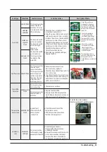
Page 26: ...ain PBA s communication circuit is faulty replace it Incorrectwire connections between the sub and main PBAs Water Leakage code High LED Flash This mayoccurwhen an alien substance is in the DVCase Sin...

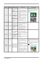
Page 27: ...t is damaged Thewire is disconnected The doorlock switch unit is defective This mayoccurdue to a defect of the main PCB HotHighLED Flash Overflowcode MidLEDFlash This mayoccurwhen thewaterlevel sensor...

Page 28: ...est emptythe unit inside If it doesn t tumble afterthe above change PCB When the problem persists change the motor Perform Quick Test Mode orQuick Spin Test Does thewasherspin If it does Check Possibl...

Page 29: ...ct Go to Board Input Test Mode Go to Quick Test Mode and do Drain Pump Test Check if there is anytwist in the hose the one between Tub and Drain Pump Check if it readsAC120Vat the pumpwhen a spin cycl...

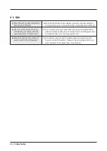
Page 30: ...rawerafterthe load is complete Is this normal A It is normal fora small amount ofwaterremaining in Detergent Drawer afterit completeswashing Also its compartment iswashed again during the following ri...

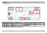
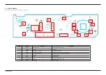
Page 31: ...MUNICATION communication with sub PBA 2 CN5 JTAG writing port 3 RY2 DOOR LOCK drive the doorlock switch 4 CN3 SMPS MODULE PowerCord AC2 N AC1 L 5 CN1 LOAD DRIVE drive the load Location Part No Functio...

Page 32: ...MP PIN4 SIDE_JET PIN5 HALL_SENSING PIN6 WATER LEVEL1 PIN7 WATER LEVEL2 PIN8 5V PIN9 GND CN7 MOTOR CONTROL PIN1 MOTOR LEFT PIN2 MOTOR RIGHT CN1 LOAD CONTROL PIN1 RINSE PIN2 HOT PIN3 COLD PIN4 CLUTCH PI...

Page 33: ...otoroperates AC120V Check Voltage at Pin 1 of CN7 and Pin 3 of CN8 When Spin mode motoroperates AC120V Pump Check Check Voltage at Pin 6 of CN1 and Pin 3 of CN8 When Drain Pump operates AC120V WaterSe...

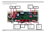
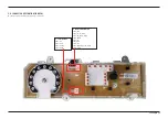
Page 34: ...ol Function Control Key and LED Function 2 SW601 Jog Dial Jog Dial 3 CN802 Wash communication Part Connect wash Main PBA 4 CN501 Conecting Sensing Part Connecting Thermistor WaterLavel and Cluch 5 LED...

Page 35: ...B This Document can not be used without Samsung s authorization CN801 COMMUNICATION PIN2 3 3V PIN3 TX_TO_MAIN PIN4 RX_FROM_MAIN PIN5 RESET PIN6 5V PIN7 GND PIN8 12V PIN9 POWER_KEY_TO_MAIN PIN10 GND CN...

Page 36: ...RAM 6 1 WIRING DIAGRAM This Document can not be used without Samsung s authorization REFERENCE INFORMATION BLK BLACK BLU BLUE GRN GREEN GRY GRAY NTR NATURAL ORG ORANGE PNK PINK RED RED SKYBLU SKYBLUE...

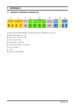
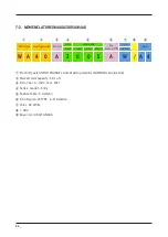
Page 37: ...orTYPE Color Buyer Grade F Code1 F Code2 F Code3 ColorCode W A 4 1 A 3 0 0 0 A W A 4 Product type CAN NOT CHANGE Auto Washing machine SAMSUNG s Guide Line Market Claim Capacity 4 1 cu ft Intro Year A...

Page 38: ...Code3 ColorCode W A 4 0 A 3 0 0 5 A W A 4 Product type CAN NOT CHANGE Auto Washing machine SAMSUNG s Guide Line Market Claim Capacity 4 0 cu ft Intro Year A Intro Year 2021 Series Grade 3 Entry Featur...

Page 39: ...anual is a property of Samsung Electronics Co Ltd Any unauthorized use of Manual can be punished underapplicable International and ordomestic law 2020 Samsung Electronics Co Ltd All rights reserved Pr...

Reviews: