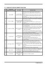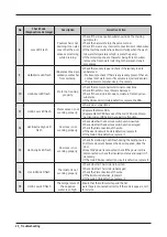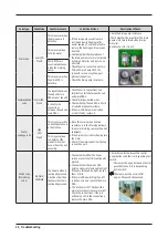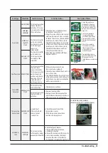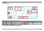
PCB Diagram _ 31
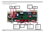
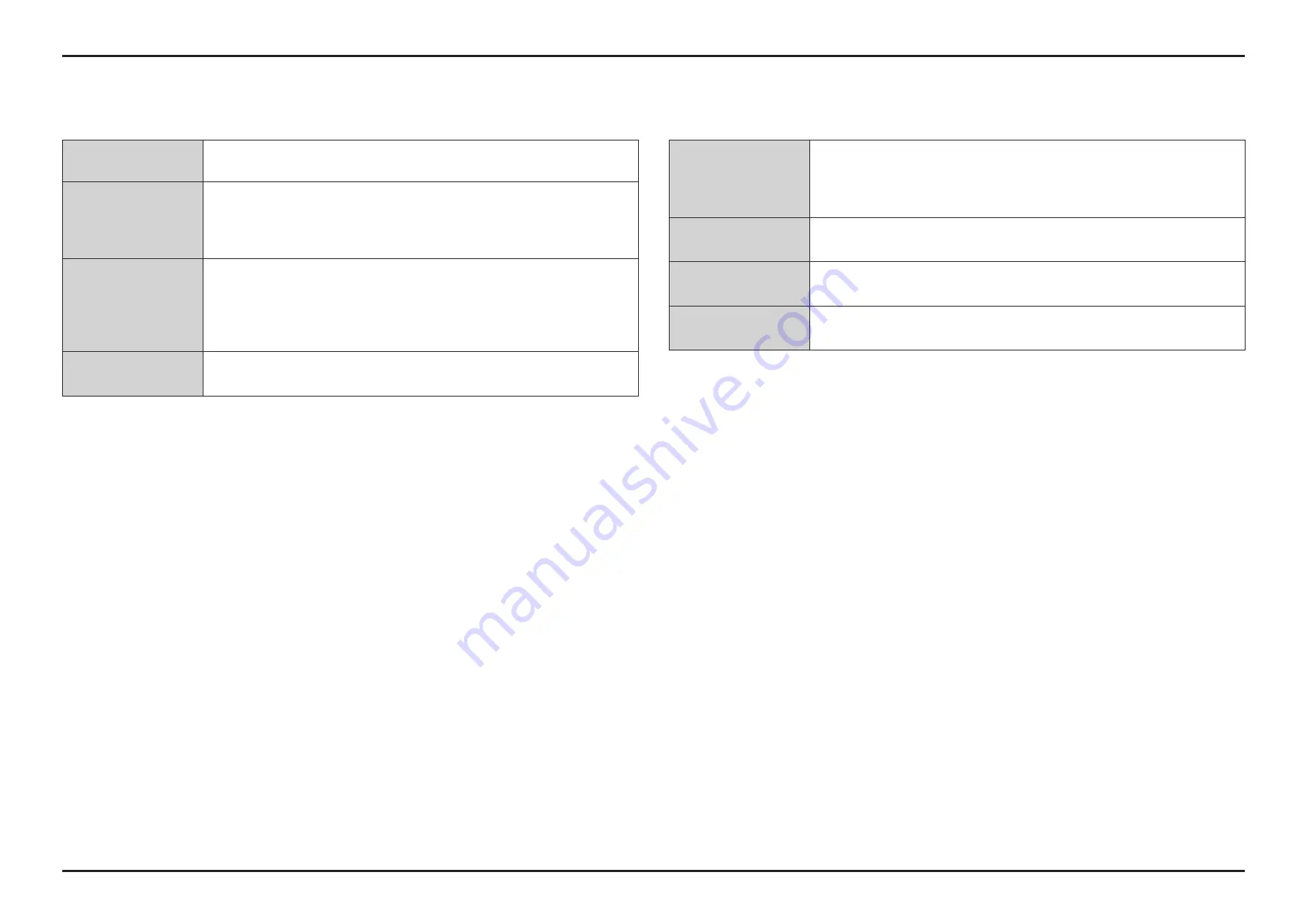
Thermistor Check
Check Resistance at Pin #3 and #9 of CN10
Tester Check = 47
㏀
TMR Sensor Check
Check Voltage at Pin #8 and Pin #1 of CN10
When spin mode = 5V DC
Check voltage at Pin #5 and Pin #1 of CN10
When spin mode and Extra Large lamp lighting up = about 2.9V DC
Motor Check
Check Voltage at Pin #1 of CN7 and Pin #3 of CN8
Check Voltage at Pin #2 of CN7 and Pin #3 of CN8
When Wash mode Motor operates = AC 120V
Check Voltage at Pin #1 of CN7 and Pin #3 of CN8
When Spin mode motor operates = AC 120V
Pump Check
Check Voltage at Pin #6 of CN1 and Pin #3 of CN8
When Drain Pump operates = AC 120V
Water Sensor Check
Check Frequency at Pin #6 and #9 of CN10
Reset frequency = 25.6KHz
Check Resistance at Pin #7 and #9 of CN10
Reset frequency = 25.6KHz
Water Valves Check
Check Voltage at Pin #1,2,3 of CN1 and Pin #3 of CN8
When Valves operates = AC 120V
Clutch-Motor Check
Check Voltage at Pin #4 of CN1 and Pin #3 of CN8
When Motor operates = AC 120V
AC Power Check
Check Voltage at Pin #1 & 3 of CN8
Tester Check = AC 120V

