


38
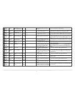
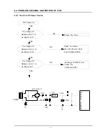
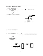
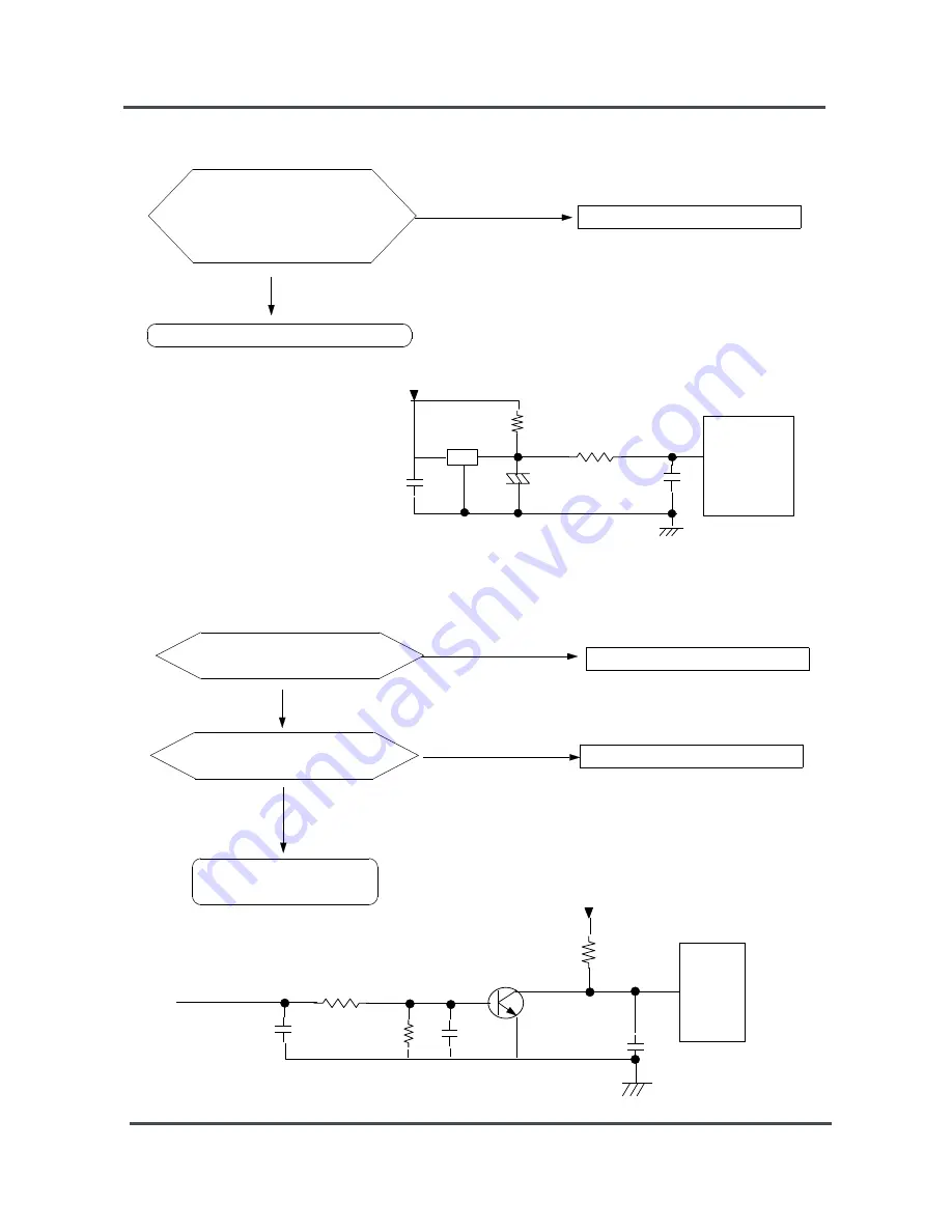
6-2-2. Reset Part
NO
YES
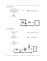
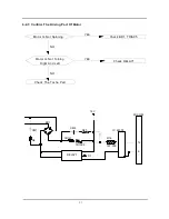
6-2-3. Interrupt Part
The Value Of
Measurement Result Of
Between Micom 25 And
Gnd Is 5V?
Check The Power Source
Check IC4
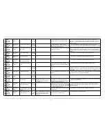
TR2
MMBT3904
67
R28 2.2K
R35 4.7K
R33
C13
C21
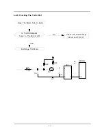
ⓐ
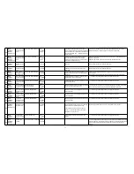
Check The Curve
Output Of
ⓐ
?
Check D11,12,16,17,18
Check The Micom
Number 67 ?
Check TR2,R35
Check The Part Of
Oscillator
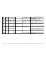
25
7533
IC4
R40 100
CE7 1UF
C15
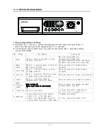
Summary of Contents for WF-F1256
Page 16: ...6 2 2 OVERVIEW OF THE WASHING MACHINE...
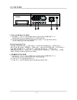
Page 19: ...9 3 PRODUCT SPECIFICATIONS 3 1 OVERVIEW OF THE CONTROL PANEL...
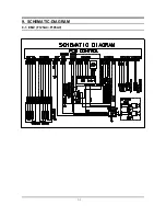
Page 42: ...50 9 SCHEMATIC DIAGRAM 9 1 EMZ F1256 F1056...
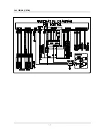
Page 43: ...51 9 2 ROLD F856...
Page 53: ...51 9 SCHEMATIC DIAGRAM 9 1 EMZ F125AC F105AV...
Page 54: ...52 9 2 ROLD F85A...
Page 55: ...51 9 SCHEMATIC DIAGRAM 9 1 EMZ F125AC F105AV...
Page 56: ...52 9 2 ROLD F85A...