background image


Version 1.0 

Samsung Electronics 

page 1 of 7 


Manual for WSNFM400A00 NFC module 


1.  Introduction 

WSNFM400A00 is applied to 13.56MHz contactless communication, including NFC functions.  

The core chipsets are from TI, part number TRF7970A and MSP430F5529. 

1. 1 Product Information 

  - Model name : WSNFM400A00 

- Operation Temperature : -20

 ~ +70


- Power : +5V 

±

10% (+4.5V ~ +5.5V) 


2. Hardware Architecture: 

2.1 Main Chipset Information 

Item 

Vendor 

Part Number 

NFC Transceiver IC 

Texas Instruments 

TRF7970A 

Mixed Signal 

MICROCONTROLLER 

Texas Instruments 

MSP430F5529 


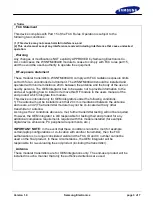
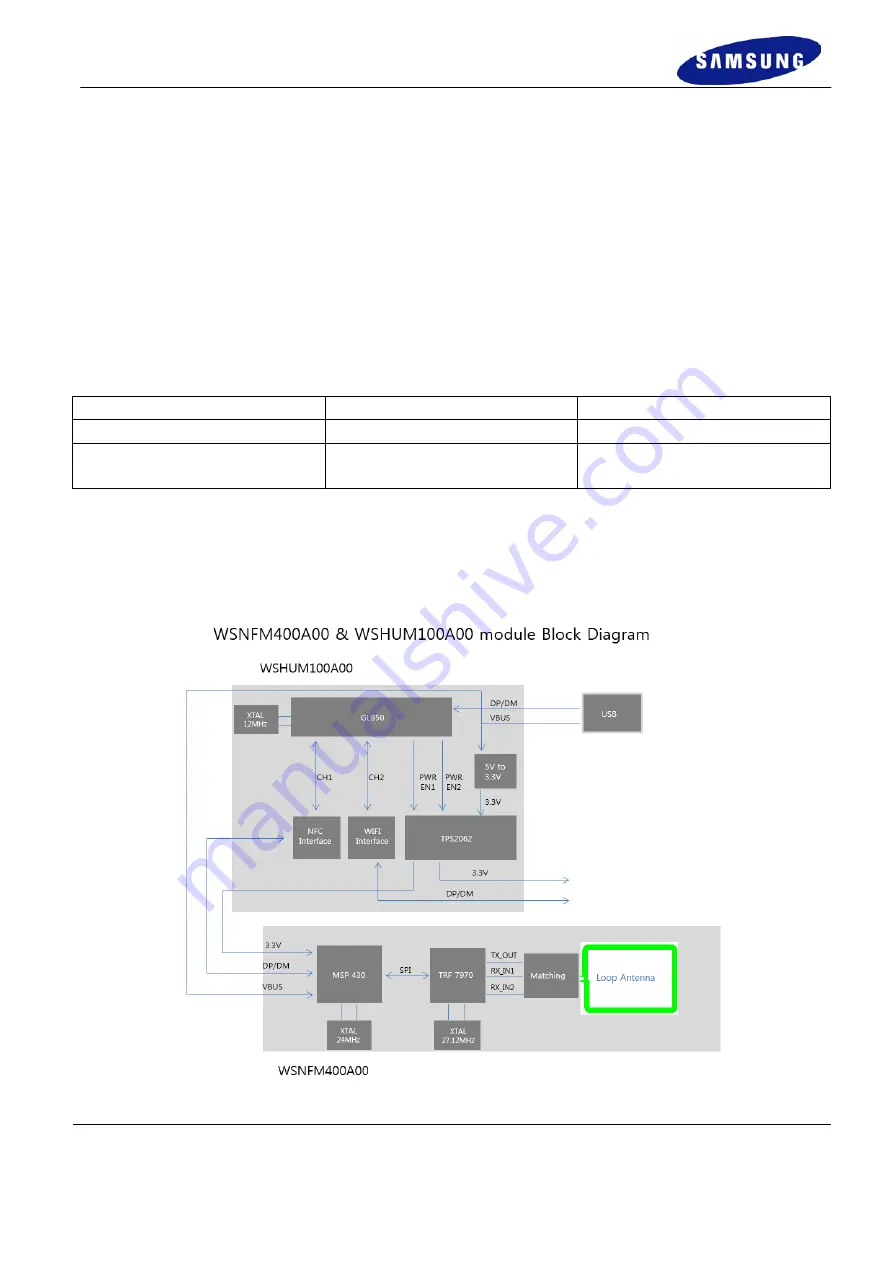
2.2 Circuit Block Diagram 

The major internal and external block diagram of WSNFM400A is illustrated in Figure 1-1. 


Figure 1-1 WSNFM400A00 block diagram and System Interface 

Summary of Contents for WSNFM400A00

Page 1: ...1 Product Information Model name WSNFM400A00 Operation Temperature 20 70 Power 5V 10 4 5V 5 5V 2 Hardware Architecture 2 1 Main Chipset Information Item Vendor Part Number NFC Transceiver IC Texas Instruments TRF7970A Mixed Signal MICROCONTROLLER Texas Instruments MSP430F5529 2 2 Circuit Block Diagram The major internal and external block diagram of WSNFM400A is illustrated in Figure 1 1 Figure 1 ...

Page 2: ...ted Protocols ISO 14443A B ISO 18000 3 Mode1 Felica NFC Type 1 2 3 4 Supported communication rate 106 212 424 848 Kbps Memory volume Flash 128KB SRAM 8KB Supported USB2 0 Time base of the RF frequency For RF frequency a crystal 27 12MHz is a clock reference Card Emulation mode NFC module acts like a standard smart card Reader mode NFC module acts like a card reader Product Details Data Modulation ...

Page 3: ...s manual of the end product which integrate this module This device is intended only for OEM integrators under the following conditions 1 The antenna must be installed such that 20 cm is maintained between the antenna and users and 2 The transmitter module may not be co located with any other transmitter or antenna As long as the 2 conditions above are met further transmitter testing will not be r...

Page 4: ...s page 4 of 7 5 Installation This NFC module must be installed in a device and not allow the user to replace nor modify it 5 Pin Connector A HUB and dongle connected to USB TO MINI USB cable A HUB and dongle connected to 5pin cable ...

Page 5: ...relocate the receiving antenna Increase the separation between the equipment and receiver Connect the equipment into an outlet on a circuit different from that to which the receiver is connected Consult the dealer or an experienced radio TV technician for help IC approval This device complies with Industry Canada license exempt RSS standard s Operation is subject to the following two conditions 1 ...

Page 6: ... 1 This module may not be co located with any other transmitters or antennas As long as 2 conditions above are met further transmitter test will not be required However the OEM integrator is still responsible for testing their end product for any additional compliance requirements with this module installed In the event that these conditions cannot be met then the FCC IC authorizations are no long...

Page 7: ...us Toutefois l intégrateur OEM est toujours responsable de tester leurs produits finis pour toutes les exigences de conformité supplémentaires avec ce module installé Dans le cas où ces conditions ne peuvent pas être remplies alors la FCC et IC autorisations ne sont plus considérés comme valides et l ID de la FCC ne peut pas être utilisé sur le produit final Dans ces circonstances l intégrateur OE...

Reviews: