
SERVICE
Manual
YEPP
Model Name : YP-P2
Model Code : YP-P2JCB/XEO
YP-P2JQW/XEO
YEPP
Refer to the service manual in the GSPN (see the rear cover) for the more information.
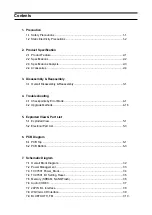
CONTENTS
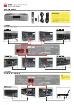
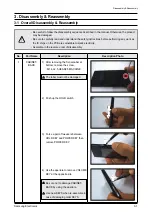
1. Precaution
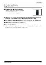
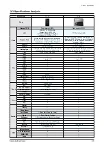
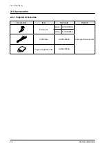
2. Product Specification
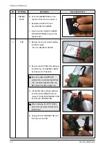
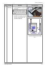
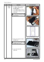
3. Disassembly & Reassembly
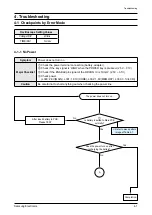
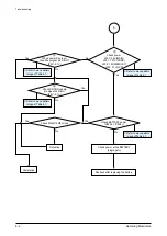
4. Troubleshooting
5. Exploded View & Part List
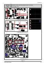
6. PCB Diagram
7. Schematic Diagram
YP-P2
Summary of Contents for YP-P2
Page 41: ...5 7 Samsung Electronics MEMO...