MP9311 User’s Guide
20
8. Set
Digital input 0 (DIN0) gates auto read action
to
Enable
.
9. Finally, set the duration of the output pulse. On the
Reader Config
interface tab,
select:
Reader Configuration
D
General Configuration
D
Operating Mode
D
Protocol Digital I/O Control
10. Enter a value in milliseconds.
11. Press
Send Changes to Reader
to reconfigure the reader with the news settings.
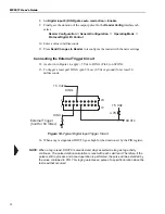
Connecting the External Trigger Circuit
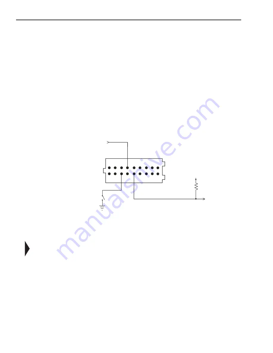
12. As shown in Figure 14, apply +5 Vdc to DIN0+ (Pin 8) on SCON1.
13. To trigger a read, pull DIN0- (pin 5) Low (0 Vdc or ground) for at least 50
milliseconds.
Figure 14–Typical Digital Input Trigger Circuit
14. When a tag is singulated, DOUT0 goes high for the duration set by the PIO register.
NOTE: When a tag is read, DOUT0 is asserted and stays asserted as long as tag activity
continues. The pulse duration calculation is reset with each valid read. Therefore, if the
pulse is still in process and a read operation is performed, the pulse will be extended by
the value contained in PIO. This logic guarantees a pulse of a specific duration since the
last read that occurred
+5 Vdc
External Trigger
(hold for 50 mSec)
4.7K
+5 Vdc
DIN0-
DIN0+
DOUT0
1
2
19
20
Summary of Contents for MP9311 Series
Page 1: ...User s Guide MP9311 Low Power UHF Reader Module THE POWER TO CHOOSE...
Page 6: ...MP9311 User s Guide iv...
Page 12: ...MP9311 User s Guide 6...
Page 34: ...MP9311 User s Guide 26...
Page 58: ...MP9311 User s Guide 50...
Page 59: ......


