MP9311 User’s Guide
30
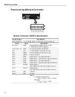
Power and Input/Output Connector
System Connector (SCON1) Specifications
Connector Type
Specification
20-Pin Dual Row
2 x 10 Header, (2x10), 1.0 mm pitch, .0.2 mm square pin
Pin No.
Name
Signal/Value
16, 18, 20
PWR
System Supply Voltage, 5.0 Vdc +/-10%,
2.3A Max (All inputs tied together)
3,10,12,14,17,19
GND
Ground (All grounds tied together)
Pin 1
V33
3.3 Vdc Output (
For factory use only
.)
Pin 2
PROG
Program Enable (
For factory use only
.)
Pin 4
RESET
Active Low Reset
Pin 5
DIN0-
Digital Input 0 – low input (see Note 1)
Pin 6
DIN1+
Digital Input 1 – high (reference) input (see Note 1)
Pin 7
DIN1-
Digital Input 1 – low input (see Note 1)
Pin 8
DIN0+
Digital Input 0 – high (reference) input (see Note 1)
Pin 9
DOUT0
Digital output 0,
open collector to ground (50 Vdc @ 40 mA max)
Pin 11
DOUT1
Digital output 1,
open collector to ground (50 Vdc @ 40 mA max)
Pin 13
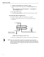
TXD
Transmit
Pin 15
RXD
Receive
NOTE 1:
To activate the digital input:
3 Vdc < (V
DINn+
– V
DINn-
) < 25 Vdc
Otherwise:
(V
DINn+
– V
DINn-
) ~ 0 Vdc
System Connector [SCON1]
1
2
19
20
1
2
19
20
Summary of Contents for MP9311 Series
Page 1: ...User s Guide MP9311 Low Power UHF Reader Module THE POWER TO CHOOSE...
Page 6: ...MP9311 User s Guide iv...
Page 12: ...MP9311 User s Guide 6...
Page 34: ...MP9311 User s Guide 26...
Page 58: ...MP9311 User s Guide 50...
Page 59: ......


