background image

MP9311 User’s Guide

38

Using the Wv Command

The Wv command is a multifunction command that performs any erase, write, and 
verification needed to program a tag in a specific protocol. The command can also lock the 
data.

The format of the 

Wv

 command is as follows:

}Wv,b:<EPC data>,u:<user memory>,m:<lock mask>!

where:

b:<EPC data> 

is the EPC ID to write to the tag.

u:<user memory>

 is the user data to be written to the tag. The number of bytes 

varies depending on the tag.

m:<lock mask> 

is the lock mask to indicate which tag field to lock. Each 4-bit 

nibble in the mask indicates the lock state to apply to a specific part of the tag. A mask 
nibble value of 1 locks the specific part of the tag. A mask nibble value of 0 indicates 
no lock is applied. 

For the ISO18000-6B protocol, the mask nibbles apply to the following fields:

To write an EPC ID value of 332233445566778899aabbcc and verify the write, enter:

}wv,b:332233445566778899aabbcc!

To write the EPC ID data and lock the data, enter:

}wv,b:332233445566778899aabbcc,m:1!

Mask Nibble

4

3

2

1

0

Tag Field

User Memory

Unused

Unused

Unused

EPC data

Summary of Contents for MP9311 Series

Page 1: ...User s Guide MP9311 Low Power UHF Reader Module THE POWER TO CHOOSE...

Page 2: ...der hardware solutions in the LF HF and UHF segments of the RFID marketplace SAMSys is a public company listed on the Toroto Stock Exchange under the symbol SMY SAMSys Technologies Inc 44 East Beaver...

Page 3: ...Wxx only 12 Selecting ETSI Frequency Bands MP9311 Wxx only 13 Single Frequency Selection 13 Frequency Hopping Selection 13 Chapter 3 Operation 15 MP9311 Power Up and Initialization 16 Setting the RF M...

Page 4: ...am a 64 Bit EPC Impinj Zuma Tags 40 Program a 48 Bit Product Code Impinj Zuma Tags 40 Program the User Data Impinj Zuma Tags 41 Change the Passcode Impinj Zuma Tags 41 Using the Wv Command 41 Programm...

Page 5: ...ystem Connector SCON1 Digital Input Output Connections 8 Typical Digital Input and Output Circuits 8 MP9311 Enclosure Dimensions 9 Low Power UHF Antennas 10 Label Programmer Antenna Dimensions 10 TPC...

Page 6: ...MP9311 User s Guide iv...

Page 7: ...Introduction This chapter provides a general description of the MP9311 Low Power UHF Reader Module Topics discussed in this chapter include the following Unpacking the Reader About the MP9311 Physical...

Page 8: ...Sys Technologies Keep the shipping materials for inspection by the carrier 3 Verify your reader package includes the following items MP9311 Low Power UHF Reader Module System documentation CD Breakout...

Page 9: ...while transmitting a modulated signal The system receiver has input bandwidths that match the hopping channel bandwidths of the corresponding transmitters and shifts frequencies in synchronization wi...

Page 10: ...along with power and I O connections The enclosure is available with or without cooling fins depending on your operational environment One MMCX type antenna port and an integral power and I O connecto...

Page 11: ...MP9311 Wxx models support both FCC and ETSI Frequencies However only ETSI is enabled when the reader leaves the factory Model Region Case Interface MP9311 NRT North America Ridges TTL MP9311 NRR Nort...

Page 12: ...MP9311 User s Guide 6...

Page 13: ...Reader Electrical Installation Connecting Power to the MP9311 Connecting an RS 232 Serial Link to the MP9311 Connecting the Digital Input and Output Lines Reader Mechanical Installation Low Power UHF...

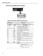
Page 14: ...ogether Pin 1 V33 3 3 Vdc Output For factory use only Pin 2 PROG Program Enable For factory use only Pin 4 RESET Active Low Reset Pin 5 DIN0 Digital Input 0 low input see Note 1 Pin 6 DIN1 Digital Inp...

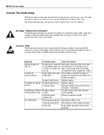
Page 15: ...1 connector is rated to withstand a maximum current of 1 0A per pin Therefore it is important that all power and ground pins be connected to prevent reader damage See Figure 4 Figure 4 System Connecto...

Page 16: ...programming information To set up the I Os to trigger tag reading and indicated tag sensing refer to the CHUMP Reference Guide and the Protocol Configuration Word PCW register Figure 6 System Connecto...

Page 17: ...um RF power and input supply voltage the MP9311 can dissipate as much as 11W of power As a result any enclosure design must dissipate the generated thermal energy and maintain the internal reader temp...

Page 18: ...ammer Antenna Dimensions Caution To prevent reader damage the RF port must be properly terminated with a 50 Ohm load or a functional UHF RFID antenna before power up Never power up the reader unless t...

Page 19: ...on allows you to easily view tag data configure the reader and perform other tag data functions In addition the RF Command Suite is the preferred method for sending CHUMP commands to a reader The RF C...

Page 20: ...dBm Setting Antenna Gain TG0 MP9311 Wxx only In order to comply with ERP and threshold limits according to EN 302 208 MP9311 Wxx models must be configured with the proper antenna gain Antenna gain is...

Page 21: ...nsmit Power Configuration TPC register For additional information on TPC register bit settings refer to Figure 11 To select Band I 869 525 MHz issue the following command to the reader Cw d TPC b 0000...

Page 22: ...requency hopping Suppress Antenna check see following Caution statement D20 D21 Reserved 24 25 26 27 28 29 30 31 Bit Name Setting Function D24 D27 D31 Suppress RXD check Warning message see Caution st...

Page 23: ...1 Low Power UHF Reader Module Topics discussed in this chapter include the following MP9311 Power Up and Initialization Setting the RF Mode Selecting Tag Protocols Enabling Tag Protocols Configuring S...

Page 24: ...key to activate Polled RF mode To halt the Auto Read or Polled Read mode press the RF Off function key Selecting Tag Protocols The MP9311 is factory configured with only those protocols selected by t...

Page 25: ...12 Protocol Selection 2 Enable or disable a protocol by using the selectors on the right side of the display and press Send Changes to Reader Configuring Specific Protocols Individual Protocol Config...

Page 26: ...er However tool settings can be changed to match your requirements Refer to the following sections and the RF Command Suite User s Guide to configure the application To configure the RF Command Suite...

Page 27: ...cate that a successful tag inventory operation was performed NOTE The tag inventory operation performs a process called singulation on the tag population and obtains the tag ID for those tags in the R...

Page 28: ...N1 13 To trigger a read pull DIN0 pin 5 Low 0 Vdc or ground for at least 50 milliseconds Figure 14 Typical Digital Input Trigger Circuit 14 When a tag is singulated DOUT0 goes high for the duration se...

Page 29: ...in the RF field of the reader 4 Select the Tag Summary interface 5 Select the protocol from the pull down above the Write Blank Tag button Figure 15 Select Tag Protocol 6 Press the Write Blank Tag but...

Page 30: ...yed Figure 18 Modify Tag Option 3 Select the Address from the pull down 4 Enter the data Length and actual Data for the specific address 5 Select if ASCII data and whether or not there is a Single tag...

Page 31: ...er 4 Troubleshooting This chapter provides general information to troubleshoot the MP9311 Low Power UHF Reader Module Topics discussed in this chapter include the following General Troubleshooting Con...

Page 32: ...Symptom Probable Cause Corrective Action Reader appears to lock up Readers are vulnerable to high ESD pulses As a result the reader can lock up Disconnect the power from the reader and reconnect The r...

Page 33: ...services including returns repairs technical support training and all other available services contact your distributor or SAMSys Customer Service at the following E mail support samsys com Telephone...

Page 34: ...MP9311 User s Guide 26...

Page 35: ...is chapter describes the specifications for the MP9311 Low Power Reader Module Information provided includes the following Reader Specifications Antenna Specifications Environmental Specifications Pow...

Page 36: ...ity 96 dBm Connections Serial RS 232 or TTL Digital I O Supply Voltage 5 0 Vdc 10 Current 0 8 2 0 Amp maximum Enclosure Material Aluminum Case Dimensions MP9311 xRx with cooling fins 2 74 x 3 74 x 0 6...

Page 37: ...50 Ohm load or a functional UHF RFID antenna before power up Never power up the reader unless the loads or antennas are connected Always power down the reader before removing an antenna or load from a...

Page 38: ...PROG Program Enable For factory use only Pin 4 RESET Active Low Reset Pin 5 DIN0 Digital Input 0 low input see Note 1 Pin 6 DIN1 Digital Input 1 high reference input see Note 1 Pin 7 DIN1 Digital Inp...

Page 39: ...from a terminal or console Information provided in this appendix includes the following Overview of the Tag Writing Command Programming the EPC1 Tag Programming the ISO 18000 6A Tag Programming the IS...

Page 40: ...ecuted with a single tag in the RF field Wt can only be used for write operations to a specific tag where the tag ID has already been assigned This command can be used for write operations to any data...

Page 41: ...ata passed in the Wa command is the kill passcode In the examples that follow this passcode is set to 00 The format of the Wa command is as follows Wa a blk addr b blk data l blks f control flag where...

Page 42: ...nd verification needed to program a tag in a specific protocol The command can also lock the data The format of the Wv command is as follows Wv b EPC data m lock mask k kill code where b EPC data is t...

Page 43: ...data l blks where a blk addr In ISO18000 6A only a single block can be written at one time and this parameter represents the specific four byte block l blks This parameter is optional since each write...

Page 44: ...g in use The Wa Wt and Wv commands can be used with the ISO18000 B tag The Wt command is used to modify data outside of the first 8 bytes in the tag and requires specification of the tag ID using the...

Page 45: ...he Implementation of EPC Tag Data on UCODE EPC 1 19 Application Note from Philips Semiconductor For detailed information on reader configuration for this tag refer to the P6B Configuration Register de...

Page 46: ...pending on the tag m lock mask is the lock mask to indicate which tag field to lock Each 4 bit nibble in the mask indicates the lock state to apply to a specific part of the tag A mask nibble value of...

Page 47: ...data This parameter is required and contains the data to write d tag ID This parameter is required for the Wt command optional for Wa and specifies the EPC code of the tag to which the write operation...

Page 48: ...e a 64 bit EPC on an Impinj Zuma EPC0 tag enter the following te wa a 1 l 1 b 5 Once the tag has been set to 64 bit use a single Wa command for subsequent Tag ID writes Wa a 4 l 5 b c80507a8009af9d710...

Page 49: ...he format of the Wv command is as follows Wv b EPC data k kill code m lock mask where b EPC data is the EPC ID to write to the tag k kill code is the kill code to be written to the reader m lock mask...

Page 50: ...writing the tag EPC ID1 This mode is the same as ID0 but every singulation returns the same bit stream The bits are random but they are seeded from the EPC Writing the EPC changes these bits The singu...

Page 51: ...alue sets PE0 for the following Use ID0 singulation with 2 blocks of random bits Retry count set to 5 set to a 1 speeds up the write process with only 1 retry Scroll first turned on Autolength EPC ena...

Page 52: ...ng overwrites any current data wa a 3 d 112233445566778899AABBCC l c To write user data to page 3 of a specific tag enter the EPC code as the d parameter singulates using ID2 so PE0 singulation bits i...

Page 53: ...col The command can also lock the data The format of the Wv command is as follows Wv b EPC data k kill code m lock mask where b EPC data is the EPC ID to write to the tag k kill code is the kill code...

Page 54: ...s at offset 2 The Gen2 tag generates the CRC 16 at power up while the Protocol Control bits The EPC ID must be set by a RFID interrogator The Protocol Control bits must be set initially on a blank tag...

Page 55: ...PC1 Gen2 tags provide SUCCESS FAIL feedback Defaults to 0 To write an EPC ID value of 332233445566778899aabbcc onto a tag with the Protocol Control field set for a 96 bit tag enter wa a 1 s 2 b 332233...

Page 56: ...ault For EPC1 Gen2 0 Reserved 1 EPC 2 TID 3 USER memory bank b blk data is the block data to write Must be 16 word multiple d tag ID is the tag identification l blks is the length in 16 bit words Defa...

Page 57: ...nibble in the mask indicates the lock state to apply to a specific part of the tag A mask nibble value of 1 locks the specific part of the tag A mask nibble value of 0 indicates no lock is applied Fo...

Page 58: ...MP9311 User s Guide 50...

Page 59: ......

Page 60: ...SAMSys Technologies Inc Part Number MP9311 01 UG V1 0 Printed in U S A THE HE P POWER OWER T TO C CHOOSE HOOSE...

Reviews: