background image

7 Troubleshooting

 Displays 

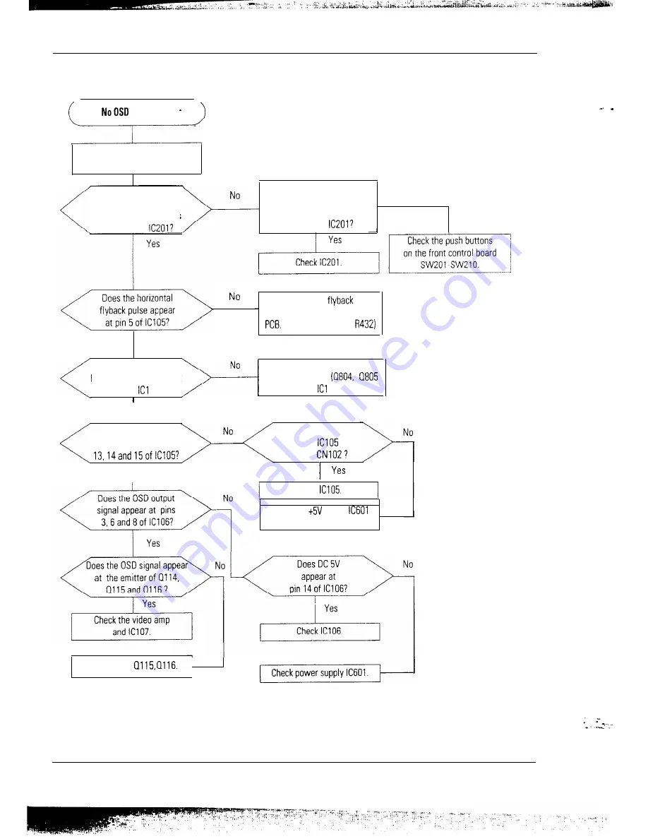
There is video but no OSD.

When pushing a front

control button, does

any pulse appear at pins

53 and 54 of 

When you push a button

on the front control panel,

does the voltage vary at pins

18 and 19 of 

No

Check horizontal 

 pulse

generation circuit on the main

 (Pin 11 of T402 and 

Yes

Goes the vertical

blanking pulse appear at

pin 10 of   OS?

Check vertical blanking pulse

generation circuit. 


and   06)

Y e s

Does the OSD video

signal appear at pins

Y e s

Does DC 5V appear at

pin 9 of 

 or

Pin 7 of 


Check 

Check DC 

 line on 

and the related circuit.


Check Ql14, 


SC-726GXL

7-5

Summary of Contents for SC-726GXL

Page 1: ... Information 3 Product Specifications 4 User Controls 5 Disassembly Reassembly 6 Alignments Adjustments 7 Troubleshooting 8 Exploded View Parts List 9 Servicing Diagrams 9 l Block Diagram 9 2 Wiring Diagram 9 3 PCB Layout and Electrical Parts List 9 4 Schematic Diagram ...

Page 2: ...ve an accurate high voltage meter available at all times Check the calibration of this meter periodically 3 High voltage should always be kept at the rated value no higher Operation at high voltages may cause failure of the picture tube or high voltage circuitry and also under certain conditions may produce X rays in excess of acceptable levels 4 When the high voltage regulator is operating proper...

Page 3: ...n The protection they give may not be obtained by replacing them with components rated for higher voltage wattage etc Parts that have special safety characteristics are identified by A on schematics and parts lists A substitute replacement that does not have the same safety characteristics as the recommended replacement part might create shock fire and or other hazards Product safety is under revi...

Page 4: ...remove the instrument s ground lead last 3 4 5 6 7 Some components are raised above the printed circuit board for safety An insulation tube or tape is sometimes used The internal wiring is sometimes clamped to prevent contact with thermally hot components Reinstall all such elements to their original position After servicing always check that the screws components and wiring have been correctly re...

Page 5: ...n generate electrical charges sufficient to damage ESDs Use only a grounded tip soldering iron to solder or desolder ESDs 8 Minimize body motions when handling unpackaged replacement ESDs Motions such as brushing clothes together or lifting your foot from a carpeted floor can generate enough static electricity to damage an ESD 9 A marks parts for ESDs on schematic diagrams and electrical parts lis...

Page 6: ...3 333 0 064 0 064 0 080 1 080 i 048 0 427 12 711 15 253 12 800 0 413 0 318 0 027 28 322 25 175 31 500 Positive Negative Separate Negative Negative Separate Negative Negative Separate Separate Sync VESA aoop5 Hz 800x600 46 875 21 333 1 616 3 232 16 162 0 323 75 000 13 333 0 064 0 448 12 800 0 021 49 500 Positive Positive Separate 1024 60 Hz 1024x768 1024P5 Hz 1024x768 48 363 60 023 20 677 i 6 660 2...

Page 7: ...ive Negative Separate w T Chart Continued Apple Mac WI75 Hz 832x624 49 726 20 110 1 117 3 910 14 524 0 559 74 551 13 414 0 060 0 784 12 549 0 020 57 284 Negative Negative Separate 1152P5 Hz 1152x870 68 681 14 560 1 280 1 440 11 520 0 320 75 062 13 322 0 044 0 568 12 667 0 044 100 000 Negative Negative Composite ISync on green Composlte T SUN lWJ76 Hz 1152x900 71 713 13 945 0 909 1 970 10 913 0 152...

Page 8: ...rmation 2 2 Semiconductor lead Identification D109 D110 0111 D301 D303 D310 D401 D402 D404 D414 D417 0515 D602 D606 0802 D803 D804 DBl DBZ DB3 DG3 DG4 DG5 DG6 DG7 DAl ZD101 20102 20103 D403 D617 0618 D619 SC726GXL 2 3 ...

Page 9: ...2 Reference Information 2 2 Semiconductor Lead Identification 2 4 SC 726GXL ...

Page 10: ... p Positive at 75 Q Terminated Separate Sync TTL level Positive Negative Sync on Green Composite Sync 0 286 Vp p 5 Negative Video on Vp p positive Composite Sync TTL level Positive Negative 135 MHz Horizontal 306 mm 3 mm 4 3 ratio 287 5 mm k 3 mm 54 Ratio Vertical 230 mm_ 3 mm AC 90 l 32 198 264 Volt 60 Hz 50 Hz 3 Hz 120 Watt Max 16 5 x 16 9 x 17 3 Inches 420 x 428 x 439 mm 21 2 x 21 5 x 21 9 Inch...

Page 11: ...3 Product Specifications 3 2 Dimensions SC 726GXL 428 mm 428 mm ___ __ _ _ _ _ 439 mm 451 f 45 Swivel angle 3 2 SC 726GXL ...

Page 12: ...tion Most video boards that operate at 1280X1024 resolution recommend using coaxial cable with BNC connectors The 5BNC connectors on the rear of the monitor can accept Red Green and Blue video Composite sync can be applied separately or combined with the Green video signal commonly referred to as composite sync on green If composite sync on green is used then only 3 of the 5 BNC connectors are use...

Page 13: ...ation Sync Select Push Once Color Temperature Control Push twice Color Control Hue Saturation Push three times Sync Select G D Geometric Distortion Push once Pincushion Trapezoid Push twice Parallelogram Tilt Size and Information Push once Size Horizontal Vertical Push twice Information Position and Modes Push once Position Horizontal Vertical Push twice User and Preset Modes The monitor features ...

Page 14: ...is occurs when you move your mouse or press a key on your keyboard This monitor is EPA Energy Star compliant and NLTTEK compliant when used with a computer equipped with VESA DPMS function If your computer system cannot support a display power management function you may purchase an optional DPMS software program to take advantage of the power saving function Please contact Samsung or your dealer ...

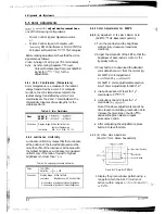
Page 15: ...abinet away to release the three tabs and pull it up and away from the monitor 4 Remove the two screws from the cabinet bottom Lift the bottom off and away from the monitor Fig 5 l 2 Removing the Video PCB 1 2 3 4 5 Remove the four connectors Sync Power Video out Color controller Remove the three screws A holding the Video PCB Ass y onto the main PCB Ass y and slide it off Remove the six screws on...

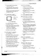
Page 16: ...ng the main PCB 8 in the PCB Bracket remove the power shaft and lift the Main PCB out Set main PCB on a smooth level surface which is protected from static electricity Figure 5 7 5 l 4 Removing the CRT Caution Do not touch the Anode 1 2 3 4 5 6 If you have not already done so remove the Main PCB Remove the eight screws securing the CRT Bracket Assembly Release the grounding wire clips from the gro...

Page 17: ...ain PCB Ass y and secure it with two screws 4 Reconnect the four connectors Color controller Video out Power Sync 5 2 3 Replacing the Main PCB 1 Set the Main PCB in the PCB bracket and secure it with eight screws 2 Hold the Main PCB Ass y close to the CRT as shown in figure 5 7 and reconnect the following connectors Function key Controller Vertical deflection yoke Horizontal deflection yoke Anode ...

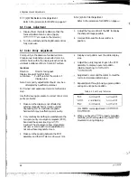
Page 18: ...he unit again in all directions If the monitor again fails to meet specifications in a non easterly direction contact your region s main service center for possible CRT replacement Testing and Burn in Mode For testing and bum in remove the signal cable from the monitor Power on the monitor and warm it up Use the bum in mode to age the monitor Power Supply Voltage AC 90 132 198 264 Volt 60 50 Hz 3 ...

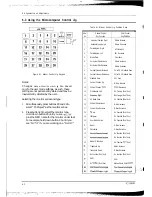
Page 19: ... Save 6 Horizontal Size Increase G Gain Increase 7 Horizontal Size Decrease G Gain Decrease 8 Vertical Linearii Increase Color CH 1 Standard Save 9 Vertical Linearii Decrease Color CH 2 Standard Save 10 Standard Save ACL Save 11 Vertical Position Up B Gain Increase 12 Vertical Position DOW EGain Decrease 13 Pinbalance Left No Function Don t Use 14 Pinbalance Right No Functicn Don t Use 15 All Mode...

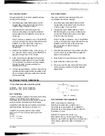
Page 20: ...er completing all standard timing mode adjustments press button 15 to save the data for all modes The monitor s microprocessor adjusts the other modes according to a predefined formula 4 5 6 Press button 5 to save the picture color data Press button 10 to save ACL data 5 Using a signal generator scan the other timing modes and make adjustments as needed Each time you make a change press button num...

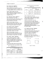
Page 21: ...6 2 and 6 3 for the tolerance range Table 6 2 Standard Mode Linearity 60 023 kHz 75 Hz 79 976 kHz 75 Hz Factory Preset Timing Modes Standard Mode Each block 5 Difference between adjacent blocks 4 8GUx6W75 Hz Hortzontal 18 2 20 1 Horizontal Less than 0 8 mm 1024x768 75 HZ Vertical 18 2 20 1 Vertical Less than 0 8 mm 12EOx1024 75Hz Horizontal 17 1 18 9 Horizontal Less than 0 7 mm Vertical 18 2 20 1 ...

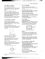
Page 22: ...ustment Direction Monitor MUST face to the East Use mechanical adjustment if correction needed is p1 5 mm With microcomputer control jig Press the tilt up button 18 or the tilt down button 19 to correct the tilt of the display Without microcomputer control jig Push the G D button twice to display the tilt OSD Push either the tilt up A or down V button to display the tilt OSD Use the up A and down ...

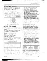
Page 23: ...only if the ratio of lowest to highest brightness is not less than 7 5 10 Table 6 5 Computing Luminance Uniformity Value 75 Min Variation x 100 Conditions Display Image White flat field Luminance Brightness cut off Contrast Max A Luminance at position of highest brightness C Luminance at position of lowest brightness 6 5 3 Color Adjustments for 9300 K 1 6 5 3 a Adjustment of the Back Raster Color ...

Page 24: ...alance differs from the above spec readjust it to within specifications When correct press buttons 5 to save 6 5 3 e ACL point Adjustment 1 2 3 4 Display the full white pattern Turn the contrast and the brightness controls fully clockwise Press buttons 3 and ACL so that the brightness is 30 l ft L Press button 10 to save the ACL setting value 6 5 4 Color Adjustments for 6500 K 6 5 4 a Back Raster ...

Page 25: ...echnicians only Use the following procedure to correct minor color purity problems Make sure the display is not affected by external magnetic fields Use an external degaussing coil to neutralize magnetic fields which may be affecting color purity Very carefully break the glue seal between the two pole purity convergence magnets PCM band and the spacer see Figure 6 10 Caution The convergence bow ma...

Page 26: ...nd blue center convergence adjustment locate the pair of 6 pole magnet rings Rotate the individual rings change the spacing between tabs to converge the vertical red and blue magenta and green lines Rotate the pair of rings maintaining the spacing between tabs to converge the horizontal red and blue magenta and green lines Don t rotate the 2 pole magnets as they adjust for color purity Mark the co...

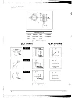
Page 27: ... 8 9 Figure 6 10 Magnet Configuration Red and Blue Alignment Red Blue and Green Alignment Qpole magnet movement 6 pole magnet movement Shii direction of I Crosshatch Pattern Crosshatch Pattern Figure 6 l 1 Magnet Movements i I 6 10 SC 726GXL ...

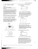
Page 28: ...d and Blue Balance Convergence I a Figure 6 14 Horizontal Line Balance Misconvergence Use a O hexdriver at the Horizontal Balance Coil Xv Turning the VR to the right raises the right end of the blue line and lowers the left end Turning the VR to the left lowers the right end of the blue line and raises the left end 6 8 4 b Vertical Red and Blue Balance Convergence BlUl Red Figure 6 15 Vertical Lin...

Page 29: ...aster appears Power circuit horizontal output circuit H V control circuit and H V output circuit High voltage develops but no raster appears Video output circuits High voltage does not develop Horizontal output circuits Horizontal line on raster No Check the power supply circuits D618 and R316 Yes Check the power supply circuits I _ fi A 7rat _ _ _ _ _ SC726GXL 7 l ...

Page 30: ...itter of Q402 No Check the push pull circuits Q402 and Q403 Yes Does drive output pulse appear at drain of Q401 Replace Cl401 or check its related circuits D407 0408 D409 and T401 Yes Check flyback pulse at collector 1 No 1 Check rhe H size Drive of Q407 connection of CN401 q and its related circuits 0410 output circuits 1 D404 Q405 Q406 and R431 ...

Page 31: ...s Yes Yes No Yes Does the pulse appear at No Check C 02 Q503 and Q505 Power indicator is orange I I Check signal cable connection y 5 g y Yes I Does H V sync output appear at pins 26 and 30 of ICZOl Check MICCIM IC201 Yes Check IC401 SC 726GXL 7 3 I i ...

Page 32: ... and 9 of IC104 on the video PC No Check signal cable signal source IC102 and IC109 Yes No Does the video amplifie pulse appear at the emitter of Q114 Q115 Q116 I I Does the DC voltage appear at pin 12 of IC104 Check contrast control circuit on video PCB R126 IF101 and Pin 6 pi of CN102 DR8 DG8 DB8 and Pins 5 9 DA7 DG7 DB7 Q114 Q115 Q116 RR15 16 17 RG15 16 17 4 i P 1 sj eri 7 4 SC 726GXL ...

Page 33: ...ck horizontal flyback pulse _ generation circuit on the main PC6 Pin 11 of T402 and R432 Yes Goes the vertical blanking pulse appear at pin 10 of ICl OS I Check vertical blanking pulse generation circuit Q804 Q805 and ICI 06 Y e s Does the OSD video signal appear at pins 13 14and15ofIC105 Y e s Does DC 5V appear at pin 9 of IC105 or Pin 7 of CN102 I 1 Yes Check IC105 Check DC t5V line on IC601 and...

Page 34: ...n This screen displays the message check signal cable along with red g een and blue boxes Use these boxes to check whether each individual color R G B is operating or not hen you push the manu degauss button does 5 V appear at pin 42 of IC201 Yes Replace IC201 Pushing manual degauss button does the II601 operate properly Replace 11601 I Yes 7 6 SC 726GXL ...

Page 35: ...nc input inactive Does 0 zero V appear at No Check 0605 HIC601 IC603 Pin13 of HICGOl and Q602 Table 9 2 DPMS Logic Table Mode Normal Stand By Suspend Off SYNC H V Video LED Color Active Active Active Green Inactive Active Blanked Orange Active Inactive Blanked Orange Green blanking Inactive inactive Blanked Orange blanking Note If signal cable is removed DPMS function does not operate and a self r...

Page 36: ...I No Check the buttons SWl SW6 and SW7 SW12 I Yes Table 9 I Front Panel Button Location Function C2 3 Pin 8alance C214 Tilt c215 Vertical Linerity C216 Horizontal Size c217 Vertical Size C218 Horizontal Position c219 Vertical Position c220 Side Pincushion c221 Trapezoid c222 Paralleiogram I f I 1 _ ...

Page 37: ...____ ____ c_ f _ __ h__ ___ ___ N N N ...

Page 38: ... 1 1 I 8 Exploded View and Parts List Memo ...

Page 39: ... t _ I_ ...

Page 40: ......

Page 41: ......

Page 42: ......

Page 43: ......

Page 44: ......

Page 45: ......

Page 46: ......

Page 47: ......

Page 48: ......

Page 49: ......

Page 50: ......

Page 51: ......

Page 52: ......

Page 53: ......

Page 54: ......

Page 55: ......

Page 56: ......

Page 57: ......

Page 58: ......

Page 59: ......

Page 60: ......

Page 61: ......

Page 62: ......

Page 63: ......

Page 64: ......

Page 65: ......

Page 66: ......

Page 67: ......

Page 68: ......

Page 69: ......

Page 70: ......

Page 71: ......

Page 72: ......

Page 73: ......

Page 74: ......

Page 75: ......

Page 76: ......

Page 77: ......

Page 78: ......

Page 79: ......

Page 80: ......

Page 81: ......

Page 82: ......

Page 83: ......

Page 84: ......

Page 85: ......

Page 86: ......

Page 87: ......

Page 88: ......

Page 89: ......

Page 90: ......

Page 91: ......

Page 92: ......

Page 93: ......

Page 94: ......

Page 95: ......

Page 96: ......

Page 97: ......

Page 98: ......

Page 99: ......

Page 100: ......

Page 101: ......

Page 102: ......

Page 103: ......

Page 104: ......

Page 105: ......

Page 106: ......

Page 107: ......

Page 108: ......

Page 109: ......

Page 110: ......

Page 111: ......

Page 112: ......

Page 113: ......

Page 114: ......

Page 115: ......

Reviews: