background image

14

Operating Procedures cont’d ...

C. 

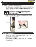
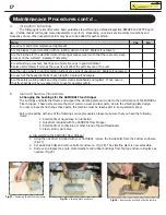
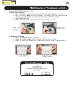
Using the SAMURAI on stairs and other diffi cult to maneuver areas

1.  Verify that handle extension is disconnected and removed from main unit.
2.  Place one hand on top handle to guide machine and other hand on side handle to gently push the unit 

along fl oor surface.

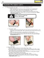
3.  Tilt machine to proper operating angle as described above by simultaneously 

gently pushing down unit with guiding hand and lifting with pushing hand.  
(Fig.17).

4.  Guide the machine in the direction required to strip the material.
5.  Consult “General principles in using the SAMURAI fl oor stripper” as detailed 

above for detailed instructions in using the SAMURAI fl oor stripper.
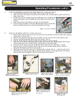
D. 

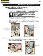
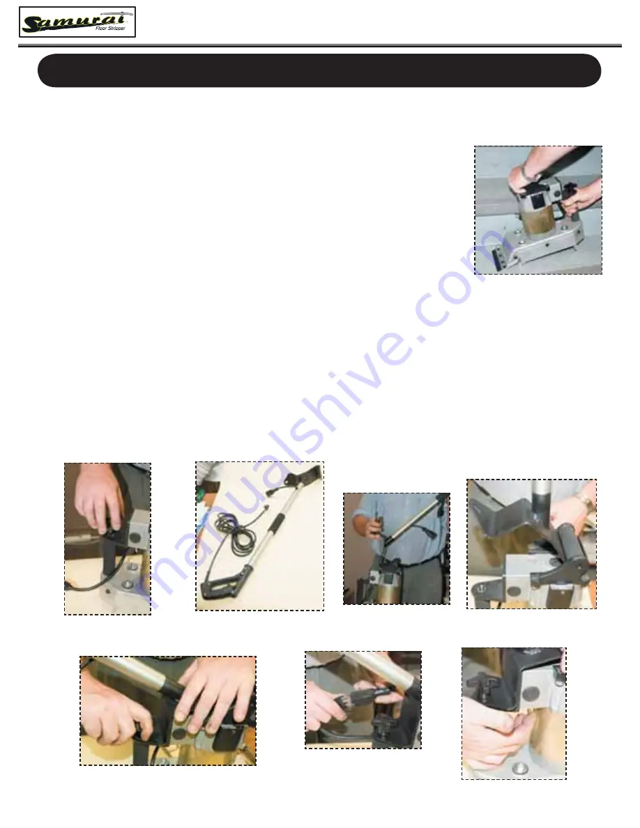
Using the SAMURAI with the handle extension

1.  Disconnect the machine from any source of power, and wait until both the motor and blade have stopped 

moving and are cool to touch.

2.  Place the unit upright on clear and safe work surface, such as a work bench or protected fl oor area.
3.  Unscrew the back handle attachment knob and set aside.  (Fig.18)  
4.  Hook the handle extension (Fig.19) as shown (Fig.20 & Fig.21) onto top handle.
5.  Press down on the base of the handle with one hand and screw the back handle attachment knob back 

onto the handle as shown in Fig 22 to attach the extension to the fl oor stripper.

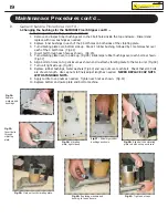
6.  Connect the lower power cord of the handle extension to that of main unit as shown.  (Fig.23)  
7.  Plug the power cord of the handle extension into a safe and grounded electrical source, directly or 

through an appropriate extension cord as required.

8.  Flip the power switch on the main unit to the ON position as shown (Fig.24).   Leave this switch in the 

ON position when using the fl oor stripper with the handle extension.  The trigger switch on the handle 
extension will act as the ON/OFF switch for the machine in this formation.

Fig.17:

  How to use the SAMURAI

Fig.18:

  Removing the 

back handle attachment knob

Fig.19:

  Handle extension.

Fig.20:

  Attaching the ex-

tension onto the SAMURAI.

Fig.21:

  Make sure that extension 

hooks on securely to top handle.

Fig.22:

  Re-attaching the back handle 

attachment know to secure handle 
extension to unit.

Fig.23:

  Connecting the power 

cord to the handle extension to 
the main unit.

Fig.24:

  Turn main 

power switch ON.

Summary of Contents for Industrial Floor Stripper

Page 1: ...LL the sections in this manual PRIOR to attempting to service maintain or operate this equipment DO NOT operate this equipment until you have read and understood all the enclosed Operator s Manual Ind...

Page 2: ...at the customer s expense Be sure to securely pack the unit and parts in a strong container Damage in transit is not covered by this warranty All approved repairs under this war ranty will be returned...

Page 3: ...nty service and notify you of any updates changes and service advisories on your product Complete this Warranty Registration Card and mail it to the address on the back of this card or fax it to SAMUR...

Page 4: ...ce Stamp Here SAMURAI Warranty Programme c o Uniquip Canada Inc North American Authorized Dealer 4101 boul Industriel Laval QC H7L 6G9 ATTN TECHNICAL SERVICE Fold along dotted line Fold along dotted l...

Page 5: ...mounts for the SAMURAI 10 A Attaching the 5 3 8 blade 11 B Attaching the 4 blade 11 C Attaching the 9 blade 11 B General principles in using the SAMURAI floor stripper 13 C Using the SAMURAI on stair...

Page 6: ...s precautions and work hazards that may and or do exist at the jobsite Powered by a 1 2 hp 5A induction electric motor the SAMURAI is an industrial use unit designed to make oor stripping fast and eas...

Page 7: ...an and should include eye and ear protection protective helmets gloves dust mask and any other items that are appropriate for the job and jobsite requirements b Never wear any jewelry neck ties or oth...

Page 8: ...stics or repairs g VIBRATIING FLOOR STRIPPER BLADES CAN CAUSE SERIOUS INJURY OR DEATH DO NOT ATTEMPT TO PERFORM ANY REPAIRS SERVICE OR DIAGNOSTICS OR TO TRANSPORT OR MOVE THE UNIT UNTIL THE BLADE AND...

Page 9: ...ght to update and modify the equipment without prior noti cation Prior to undertaking to perform any maintenance or repair procedures please contact our Technical Support Hotline for clari cation and...

Page 10: ...5 Parts Breakdown...

Page 11: ...on Roller 2 21 SA 21 1 4 Nylon Tube 2 22 SA 22 Axle Bolt for Nylon Rollers 1 23 SA 23 Top Handle Bar 1 24 SA 24 Support Washer 8 25 SA 25 Lower Rubber Bushing for Vibrating Plate 4 26 SA 26 Rubber Sho...

Page 12: ...ion Handle 1 56 SA 56 Power Cord Strain Relief 1 57 SA 57 M6X32 Bolts for Plastic Handle 2 58 SA 58 M4X12 Screw 3 59 SA 59 Plastic Handle 2 60 SA 60 Main Motor Connector 1 61 SA 61 Threaded Inserts 5...

Page 13: ...you have any questions please do not hesitate to contact your local authorized service centre for further assistance SAMURAI LABEL01 Qty Required 1 4 3 3 4 6 2 O NOT USE TO FORCE MACHINE TO MOVE LLOW...

Page 14: ...ired parts and contact your authorized service centre for replacement parts and further assistance to service the unit PRIOR to any further use ii Is the machine particularly the cutting blade and sup...

Page 15: ...and conforming to local safety codes Extension cords must be a 3 pole cord with a 3 pole plug and socket rated for outdoor use Our recommendation is as follows A Up to 100 ft 14 AWG B Up to 200 ft 12...

Page 16: ...e iii Using the nut driver included with the SAMURAI tighten down each bolt such that the blade is securely sandwiched in between the top mount and the vibrating plate DO NOT OVERTIGHTEN BOLTS Fig 7 F...

Page 17: ...ges on blades are facing the right direction Blade is sharpened on BOTH sides Take care when handling Fig 8 Ensure that all necessary pieces are available Fig 9 Fasten support mount to plate extension...

Page 18: ...dle extension pull on trigger 7 Proceed as fast as the machine will allow DO NOT FORCE MACHINE TO MOVE AT ANY OTHER RATE The nylon wheels at the bottom of the machine Fig 16 are designed to allow the...

Page 19: ...ide Fig 18 4 Hook the handle extension Fig 19 as shown Fig 20 Fig 21 onto top handle 5 Press down on the base of the handle with one hand and screw the back handle attachment knob back onto the handle...

Page 20: ...WNWARD PRESSURE TO HANDLE EXTENSION The oor stripper is designed neither to support the weight of the operator nor to be used to perform any function beyond those described in the Pre Operating Note S...

Page 21: ...he job and jobsite requirements 4 Ensure that the technician has tied back or remove any loose hair clothing and any other potential hazards and obstructions The SAMURAI is designed to be a low mainte...

Page 22: ...of use other inspection points may have to be added for each machine B General Service Procedures 1 Changing the bushings for the SAMURAI Floor Stripper The bushings and bolts that frame and support t...

Page 23: ...bolt bushing and washer to ensure that they are in good condition showing even wear If not set aside and take note to order replacements 6 Remove the vibrating plate from the machine Fig 31 7 Inspect...

Page 24: ...bushings over each bolt as shown Fig 37 6 Align bolts to holes on top enclosure as shown and re attach vibrating plate to the main unit Fig 38 7 Turn unit right side up Fig 39 8 Replace rubber bushing...

Page 25: ...mage any parts 3 Changing Nylon Wheels 1 Remove and inspect axle bolt for nylon wheels Fig 44 2 Replace worn wheels taking care to insert wheels in order as shown Fig 45 3 Replace nut tighten until bo...

Page 26: ...21 Notes...

Page 27: ...22 Notes...

Page 28: ...served English Service T 1 888 332 4012 F 1 866 567 0956 French Service T 1 800 332 4012 F 1 866 825 2221 Technical Support Hotline c o Technical Service Uniquip Canada Inc SAMURAI North American Auth...

Reviews: